


INSTALLATION AND WIRING
25
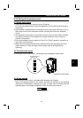
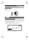
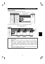
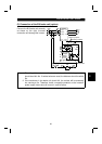
(4) LED Status Indicator
The LED Status indicator provides information on the status of operation of the
inverter. The status information is shown in the below table. The indicator has five
states; Off, Blinking Green, Steady Green, Blinking Red, and Steady Red.
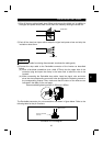
After connecting the drop cable to the trunk of the active network, observe the
condition of the Status LED. The inverter unit uses the Combined Module/Network
status LED scheme described in the DeviceNet communications standard.
LED Status indication
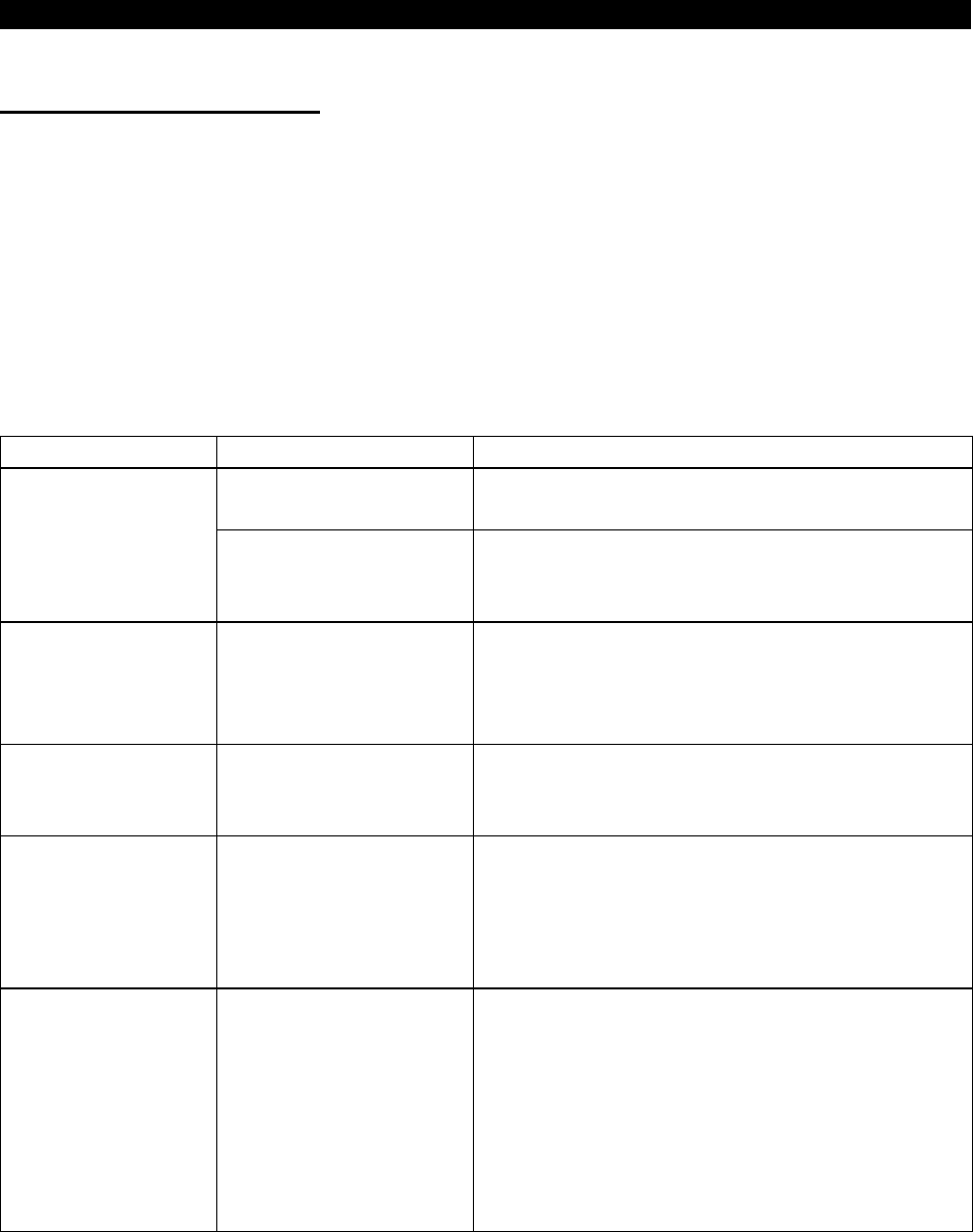
LED CONDITION STATE OF SYSTEM NOTE
Inverter power off
Network power on
Turn the inverter power on. The inverter will
then complete duplicate node address test.
Off
Power on the inverter
when network Power is
off.
Turn the network power on. The inverter unit
will then complete duplicate node address test.
Blinking Green Connection not yet
established by master
Though the inverter power is on and it has
been confirmed that there is no same node
address, the master has not yet established a
communication link.
Steady Green Network and inverter
power on, connection
established by master
A master device on the network has designated
the inverter unit for communications. The LED
also holds this state during communication.
Blinking Red Connection time-out The master station has selected this inverter
unit for communication (LED is green).
However, no response is given within the
waiting time (Note) set in EPR. Check the
master for disconnection from the network.
Steady Red Critical link failure Failed communication device
•
Duplicate station number
•
Network power off
•
Cable from option unit to network not
connected or severed.
•
Inverter unit is only node on network
•
Network damaged
Must cycle power to recover from this fault.
Note: Time Limit = 4 × EPR (EXPECTED PACKET RATE)
It should be noted that this EPR is the EPR set by the DeviceNet master. This
does not refer to the bit setting of EPR in Pr. 347.