


92
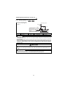
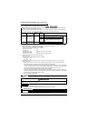
Operation selection functions 1 (Pr. 17 to Pr. 37)
3.5.5 Regenerative brake duty (Pr. 30, Pr. 70 )
<Setting>
1) When using the built-in brake resistor, brake unit or power regeneration converter
Set "0" in Pr. 30. The Pr. 70 setting is made invalid.
At this time, the regenerative brake duty is as follows.
•FR-V520-1.5K to 3.7K................... 3%
•FR-V520-5.5K ............................... 2%
•FR-V520-7.5K or more.................. 0% (without a built-in brake resistor)
•FR-V540-1.5K to 5.5K................... 2%
•FR-V540-7.5K or more.................. 0% (without a built-in brake resistor)
2) When using the high-duty brake resistor (FR-ABR)
• Set "1" in Pr. 30.
• Set Pr.70 "special regenerative brake duty" as follows:
7.5K or less . . . .10%
11K or more . . .6%
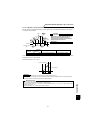
3) When using the high power factor converter (FR-HC) or power regeneration common converter (FR-CV)
1. Set "2" in Pr. 30.
2. Use any of Pr. 180 to Pr. 183 and Pr. 187 to assign the following signals to the contact input terminals.
•X10: FR-HC connection, FR-CV connection (inverter operation enable signal)
To make protective coordination with the high power factor converter (FR-HC) or power regeneration
common converter (FR-CV), use the inverter operation enable signal to shut off the inverter output. Enter
the RDY signal of the high power factor converter or power regeneration common converter.
•X11: FR-HC connection (instantaneous power failure detection signal)
When the computer link plug-in option (FR-A5NR) is used and the setting is made to hold the pre-
instantaneous power failure mode, use this signal to hold that mode. Enter the instantaneous power failure
detection signal of the high power factor converter.
3. The Pr. 70 setting is made invalid.
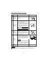
z When making frequent starts/stops in a 15K or less inverter, use the optional "high-duty brake resistor (FR-
ABR)" to increase the regenerative brake duty.
z Use the optional "high power factor converter (FR-HC) or power regeneration common converter (FR-CV)"
to reduce harmonics, improve the power factor, or continuously use the regenerative mode.
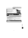
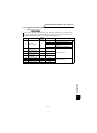
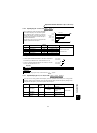
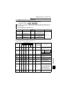
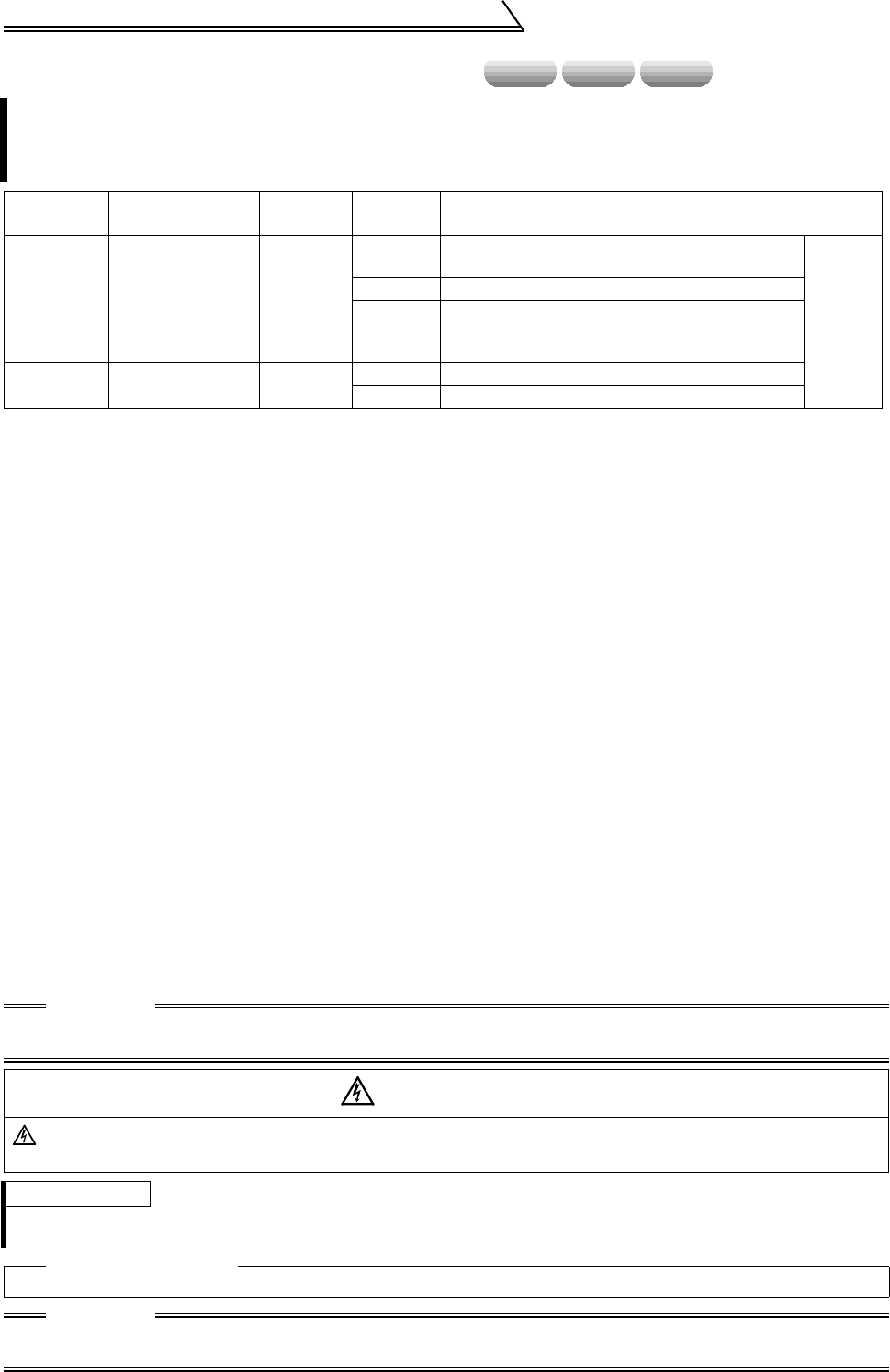
Parameter Name
Factory
Setting
Setting
Range
Remarks
30
Regenerative
function selection
0
0
When using built-in brake resistor or brake unit
(Type FR-BU, BU)
Extended
mode
1 When using the high-duty brake resistor (FR-ABR)
2
When using the high power factor converter (FR-
HC) or power regeneration common converter
(FR-CV)
70
Special regenerative
brake duty
0%
0 to 15% 1.5K
0 to 30% 2.2K or more
CAUTION
Set "10" and "11" in any of Pr. 180 to Pr. 183 and Pr. 187 to assign the terminals used to input the X10 and
X11 signals.
WARNING
The value set in Pr. 70 must not exceed the setting of the brake resistor used.
Otherwise, the resistor can overheat.
REMARKS
1. The Pr. 70 setting is invalid for the inverter of 18.5K or more.
2. Pr. 70 "regenerative brake duty" indicates the %ED of the built-in brake transistor operation.
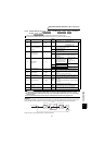
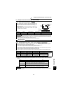
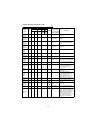
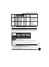
Related parameters
• X10, X11 signal terminal assignment ⇒ Pr. 180 to Pr. 183, Pr. 187 (input terminal function selection) (Refer to page 150.)
CAUTION
Changing the terminal assignment with any of Pr. 180 to 183 and Pr. 187 may affect the other functions.
Please make setting after confirming the function of each terminal.
speed torque position