


14
Others
1.6.2 Power off and magnetic contactor (MC)
(1) Inverter primary side magnetic contactor (MC)
On the inverter primary side, it is recommended to provide an MC for the following purposes.
( Refer to the Instruction Manual (basic) for selection.)
1) To release the inverter from the power supply when the inverter protective function is activated or the drive
becomes faulty (e.g. emergency stop operation)
When cycle operation or heavy-duty operation is performed with an optional brake resistor connected,
overheat and burnout of the discharging resistor can be prevented if a regenerative brake transistor is
damaged due to insufficient heat capacity of the discharging resistor and excess regenerative brake duty.
2) To prevent any accident due to an automatic restart at restoration of power after an inverter stop made by a
power failure
3) To rest the inverter for an extended period of time
The control power supply for inverter is always running and consumes a little power. When stopping the
inverter for an extended period of time, powering off the inverter will save power slightly.
4) To separate the inverter from the power supply to ensure safe maintenance and inspection work
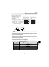
Since the MC on the inverter input side is used for the above purposes, they correspond to the standard duties.
Therefore, when making an emergency stop during running, select a JEM1038 class AC3 MC for the inverter
input side currents.
.
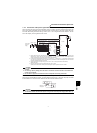
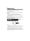
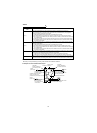
(2) Handling of secondary side magnetic contactor
In principle, do not provide a magnetic contactor between the inverter and motor and switch it from off to on during
operation. If it is switched on during inverter operation, a large inrush current may flow, stopping the inverter due to
overcurrent shut-off. When an MC is provided for switching to the commercial power supply, for example, switch it
on/off after the inverter and motor have stopped.
REMARKS
The MC may be switched on/off to start/stop the inverter. However, since repeated inrush currents at power on will shorten the
life of the converter circuit (switching life is about 100,000 times), frequent starts and stops must be avoided. Turn on/off the
inverter start controlling terminals (STF, STR) to run/stop the inverter.
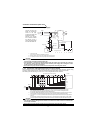
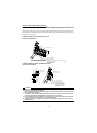
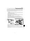
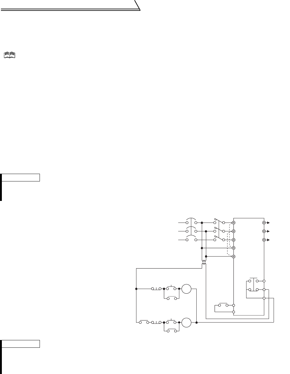
z Inverter start/stop circuit example
As shown on the right, always use the start
signal (turn on/off terminals STF, STR-SD) to
start/stop the inverter.
(Refer to page 26.)
REMARKS
*1. When the power supply is 400V class, install a step-down transformer.
*2. Connect the power supply terminals R1, S1 to the primary side of the MC to hold an alarm signal when the inverter's
protective circuit is activated. At this time, remove jumpers across terminals R-R1 and S-S1. (Refer to page 10 for
removal of jumpers)
MCCB
OFF
ON
MC
MC
RA
U
V
W
SD
MC
STF(STR)
RA
RA
MC
T
A
B
C
Power
supply
To moto
r
Inverter
Start/Stop
OFF
Operation
Operation ready
*2
*1
R
S
T
R1
S1