


134
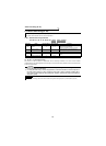
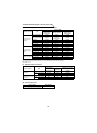
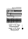
Communication functions (Pr. 117 to Pr. 124, Pr. 342)
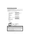
(5) Instructions for the program
1) When data from the computer has any error, the inverter does not accept that error. Hence, in the user
program, always insert a retry program for data error.
2) All data communication, e.g. run command or monitoring, are started when the computer gives a
communication request. The inverter does not return any data without the computer's request. Hence, design
the program so that the computer gives a data read request for monitoring, etc. as required.
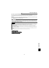
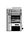
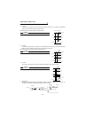
3) Program example
When the operation mode is switched to communication operation
CAUTION
When the inverter's communication time interval is not set, interlocks are provided to disable
operation to prevent hazard. Always set the communication check time interval before starting
operation.
Data communication is not started automatically but is made only once when the computer provides a
communication request. If communication is disabled during operation due to signal cable breakage
etc., the inverter cannot be stopped. When the communication check time interval has elapsed, the
inverter will come to an alarm stop (E.PUE).
The inverter can be coasted to a stop by turning on its RES signal or by switching power off.
If communication is broken due to signal cable breakage, computer fault, etc. the inverter does not
detect such a fault. This should be fully noted.
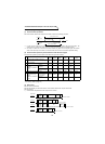
10 OPEN "COM1:9600,E,8,2,HD" AS #1
20 COMST1,1,1:COMST1,2,1
30 ON COM(1)GOSUB
*
REC
40 COM(1)ON
50 D$= "01FB10002"
60 S=0
70 FOR I=1 TO LEN(D$)
80 A$=MID$(D$,I,1)
90 A=ASC(A$)
100 S=S+A
110 NEXTI
120 D$=CHR$(&H5)+D$+RIGHT$(HEX$(S),2)
130 PRINT#1,D$
140 GOTO 50
1000
*
REC
1010 IF LOC(1)=0 THEN RETURN
1020 PRINT "RECEIVE DATA"
1030 PRINT INPUT$(LOC(1),#1)
1040 RETURN
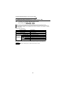
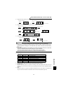
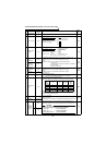
10
40
50
140
1000
1040
Initial setting of I/O file
: Communication file opening
: Circuit control signal (RS, ER) ON/OFF setting
: Interrupt definition at data receive
: Interrupt enable
Transmission data setting
Sum code calculation
: Addition of control and sum codes
Data transmission
Interrupt data receive
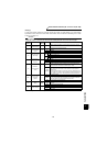
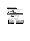
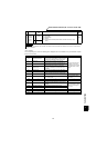
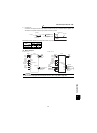
General flowchart
Line number
I/O file
initial setting
Receive data processing
Data import
Screen display
: Interrupt occurrence at data receive
Interrupt
Transmission data processing
Data setting
Sum code calculation
Data transmission
to
to to