


37
Design information to be checked
WIRING
1
1.10 Design information to be checked
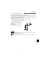
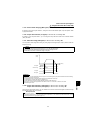
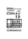
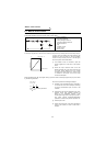
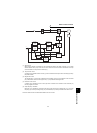
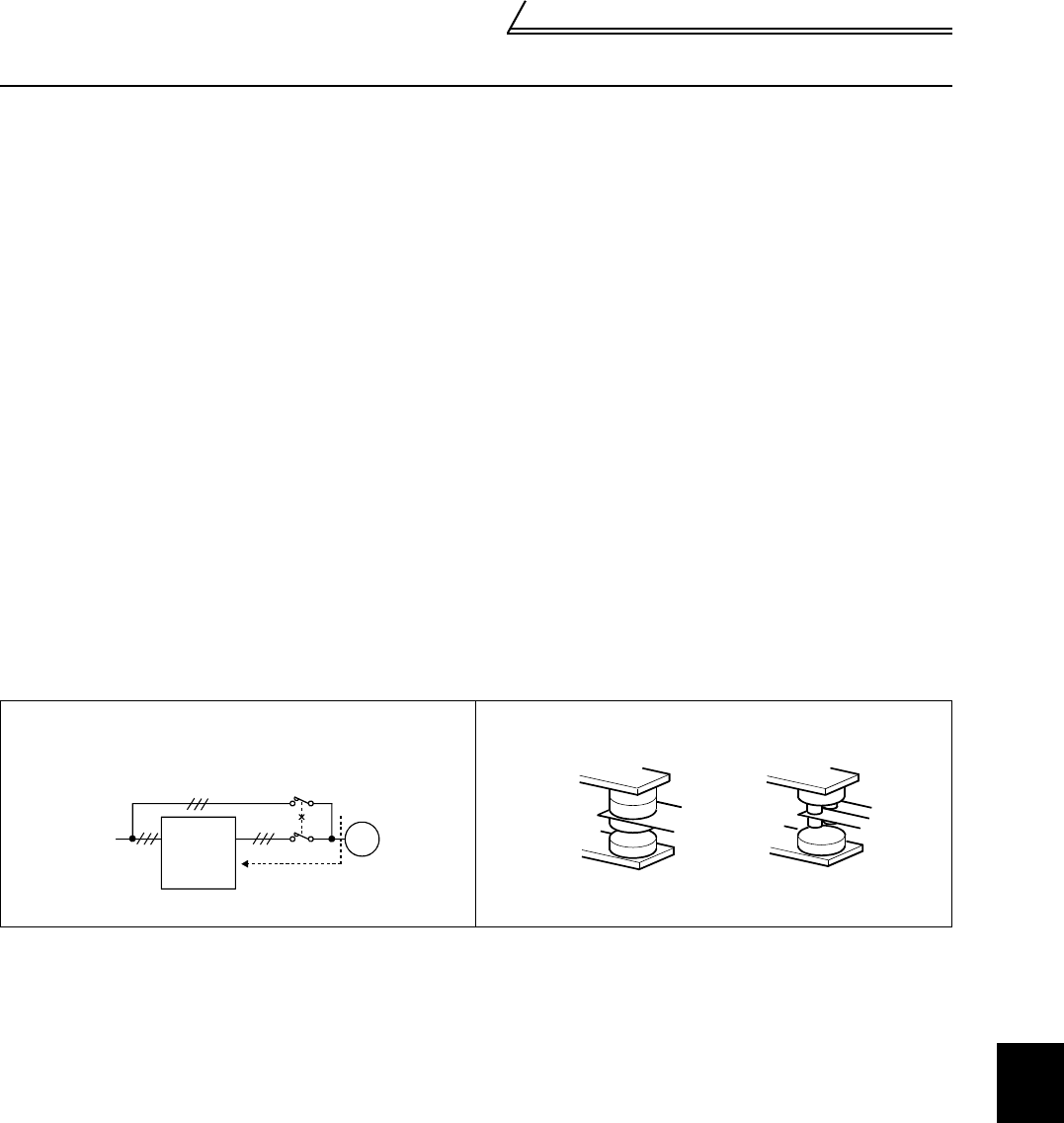
1) When performing bypass operation for the motor other than the vector control dedicated motor, securely
provide electrical and mechanical interlocks for the MC1 and MC2 used for bypass.
When the wiring is wrong or there is a bypass circuit as shown below, the inverter will be damaged by a sneak
current from the power supply due to arcs generated at the time of switchover or chattering caused by a
sequence error.
2) If the machine must not be restarted when power is restored after a power failure, provide a magnetic contactor
in the inverter's primary side and also make up a sequence that will not turn on the start signal.
If the start signal (start switch) remains on after a power failure, the inverter will automatically restart as soon as
the power is restored.
3) When the power supply used with the control circuit is different from the one used with the main circuit, make
up a circuit which will switch off the main circuit power supply terminals R, S, T when the control circuit power
supply terminals R1, S1 are switched off.
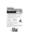
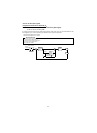
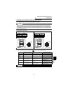
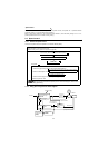
4) Since the input signals to the control circuit are on a low level, use two parallel low-level signal contacts or a
twin contact for contact inputs to prevent poor contact.
5) Do not apply a voltage to the contact input terminals (e.g. STF) of the control circuit.
6) Do not apply a voltage directly to the alarm output terminals (A, B, C). Always apply a voltage to these
terminals via a relay coil, lamp, etc.
7) Fully make sure that the specifications and rating match the system requirements.
Bypass
(other than the vector control dedicated motor)
Low-level signal contacts
Inverter
Sneak current
Interlock
Power
supply
MC2
MC1
U
V
W
IM
R
S
T
Low-level signal contacts Twin contact