


6
Connection of stand-alone option units
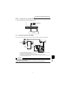
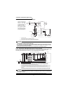
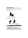
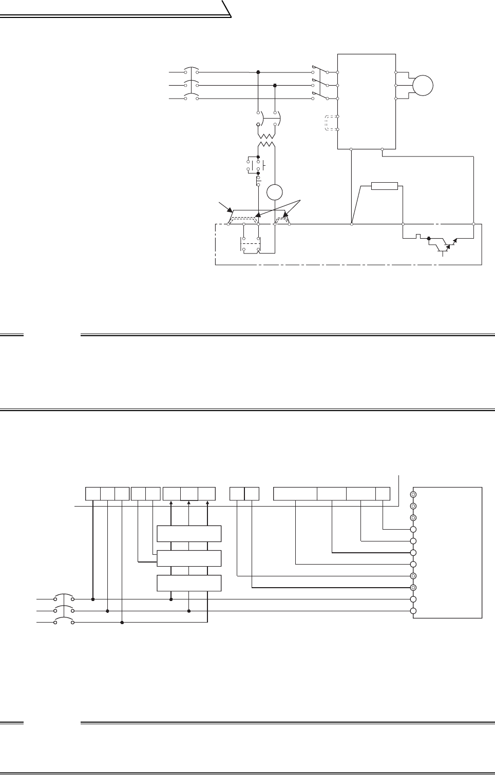
1.3.3 Connection of the brake unit (BU type)
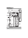
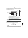
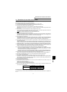
1.3.4 Connection of the high power factor converter (FR-HC)
When connecting the high power factor converter (FR-HC) to suppress power supply harmonics, perform wiring
securely as shown below. Incorrect connection will damage the high power factor converter and inverter.
After making sure that the wiring is correct, set "2" in Pr. 30 "regenerative function selection".
*1 Connect the inverter terminals (P, N) and brake unit (BU type) terminals so that their terminal signals match with each
other. (Incorrect connection will damage the inverter.)
*2 When the power supply is 400V class, install a step-down transformer.
*3 For capacity 5.5K or less, remove the jumper across terminals PR-PX.
CAUTION
• The wiring distance between the inverter, brake unit and resistor unit should be within 2m . If twisted
wires are used, the distance should be within 5m.
• If the transistors in the brake unit should become faulty, the resistor can be unusually hot, causing a
fire. Therefore, install a magnetic contactor on the inverter's power supply side to configure a circuit
so that a current is shut off in case of fault.
• Do not remove a jumper across terminal P and P1 except when connecting a DC reactor.
*1 Remove the jumpers across the inverter terminals R-R1, S-S1, and connect the control circuit power supply to the R1
and S1 terminals. Always keep the power input terminals R, S, T open. Incorrect connection will damage the inverter.
(E.OPT (option alarm) will occur. (Refer to the Instruction Manual (basic).))
*2 Do not insert the MCCB between terminals P-N (P-P, N-N). Connect the inverter terminals (P, N) and high power factor converter
(FR-HC) terminals so that their terminal signals match with each other. (Incorrect connection will damage the inverter.)
*3 Use Pr. 180 to Pr. 183, Pr. 187 (input terminal function selection) to assign the terminals used for the X10 (X11) signal. (Refer to
page 150.)
For communication where the start command is sent only once, e.g. when used with the computer link plug-in option (A5NR),
use the X11 signal when making setting to hold the mode at occurrence of an instantaneous power failure. (Refer to page 92.)
CAUTION
• The voltage phases of terminals R, S, T and terminals R4, S4, T4 must be matched.
• Use sink logic (factory setting) when the FR-HC is connected. The FR-HC cannot be connected when
source logic is selected.
• Do not remove a jumper across terminal P and P1 except when connecting a DC reactor.
Connect the BU type
brake unit correctly as
shown on the right.
Incorrect connection will
damage the inverter.
Remove the jumpers
from terminals HB-PC
and TB-HC and fit a
jumper across terminals
PC-TB of the brake unit.
Motor
Inverter
BU type brake unit
Remove
jumpers.
T*2
*3
*1
MC
U
V
W
HCHBHA TB P
OCR
PR
MCCB
PR
PX
PC
ON
OFF
MC
OCR
N
MC
Remove
jumpers.
IM
Discharging resistor
Fit a jumper.
Power
supply
R
S
T
N
P
From FR-HCL02
Power
supply
MCCB
RST R4S4T4 N
P
Y1 or Y2 RDY RSO SE
High power factor converter (FR-HC)
Inverter
X10 *3
RES
SD
Outside box
FR-HCL01
R4
S4
T4
R3 S3 T3
R2
S2
T2
R
S
T
MC2
MC1
MC1MC2
X11 *3
*2
R1
S1
T
S
R
P
N
*1
*1