


II
1.8.13 Output stop (MRS signal): Pr. 180 to Pr. 183, Pr. 187 setting "24" ..................................................32
1.8.14 Start self-holding selection (STOP signal): Pr. 180 to Pr. 183, Pr. 187 setting "25".........................32
1.8.15 Control mode changing (MC signal): Pr. 180 to Pr. 183, Pr. 187 setting "26"..................................33
1.8.16 Torque limit selection (TL signal): Pr. 180 to Pr. 183, Pr. 187 setting "27" ......................................33
1.8.17 Start time tuning (X28 signal): Pr. 180 to Pr. 183, Pr. 187 setting "28" ............................................33
1.8.18 Torque bias selection 1 (X42 signal): Pr. 180 to Pr. 183, Pr. 187 setting "42"
Torque bias selection 2 (X43 signal): Pr. 180 to Pr. 183, Pr. 187 setting "43" .................................33
1.8.19 P control selection (P/PI control switchover) (X44 signal):
Pr. 180 to Pr. 183, Pr. 187 setting "44" ............................................................................................34
1.9 How to use the output signals (assigned terminals DO1 to DO3, ABC)
(Pr. 190 to Pr. 192, Pr. 195)................................................................................ 35
1.10 Design information to be checked ................................................................... 37
1.11 Using the second motor .................................................................................... 38
1.11.1 Wiring diagram (second motor)........................................................................................................38
1.11.2 Second motor setting parameters ...................................................................................................38
1.12 Using the conventional motor and other motors............................................ 39
1.12.1 Conventional motor (SF-VR, SF-JR with encoder) ..........................................................................39
1.12.2 Precautions for and wiring of the motor with encoder (SF-JR with encoder) ...................................40
2 VECTOR CONTROL 41
2.1 What is vector control? ..................................................................................... 42
2.2 Speed control ..................................................................................................... 44
2.2.1 Outline of speed control ...................................................................................................................44
2.2.2 Easy gain tuning function block diagram..........................................................................................44
2.3 Fine adjustment of gains for speed control .................................................... 45
2.3.1 Control block diagram ......................................................................................................................45
2.3.2 Concept of adjustment of manual input speed control gains............................................................46
2.3.3 Speed control gain adjustment procedure (Pr. 820, Pr. 821)...........................................................46
2.3.4 Troubleshooting................................................................................................................................47
2.3.5 Speed feed forward control, model adaptive speed control (Pr. 828, Pr. 877 to Pr. 881)................49
2.4 Torque control.................................................................................................... 51
2.4.1 Outline of torque control...................................................................................................................51
2.5 Fine adjustment for torque control .................................................................. 52
2.5.1 Control block diagram ......................................................................................................................52
2.6 Gain adjustment for torque control.................................................................. 53
2.6.1 Concept of torque control gains .......................................................................................................53
2.6.2 Gain adjustment procedure..............................................................................................................53
2.6.3 Troubleshooting................................................................................................................................54
2.7 Position control (Pr. 419 to Pr. 430, Pr. 464 to Pr. 494) .................................. 55
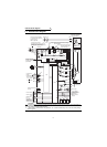
2.7.1 Connection diagram .........................................................................................................................55
2.7.2 Position control step.........................................................................................................................56
2.7.3 Control block diagram ......................................................................................................................57
2.7.4 Parameter.........................................................................................................................................57
2.7.5 Conditional position feed function by contact input (Pr. 419 = 0) .....................................................59
2.7.6 Setting the electronic gear................................................................................................................60
2.7.7 In-position width (Pr. 426) ................................................................................................................62
2.7.8 Excessive level error (Pr. 427) .........................................................................................................62