


136
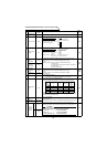
Communication functions (Pr. 117 to Pr. 124, Pr. 342)
3
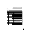
Alarm definition
all clear
HF4 H9696: Clears the error history. 4 digits
4 Run command HFA 2 digits
5
Inverter status
monitor
H7A
* Output data varies with the settings of Pr. 190 to Pr. 192 and Pr. 195.
2 digits
6
Set speed
write
(E
2
PROM)
HEE
HFF=0
H0000 to H1C20: 1r/min increments (hexadecimal) (4 digits)
HFF=1
H0000 to H11940: 0.1r/min increments (hexadecimal) (6 digits)
(0 to 3600r/min)
To change the running speed consecutively, write data to
the inverter RAM.
(Instruction code: HED)
4 digits
(6 digits)
Set speed
write (RAM)
HED
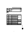
7
Set speed
(E
2
PROM)
read
H6E
HFF = 0
H0000 to H1C20: 1r/min increments (hexadecimal) (4 digits)
HFF = 1
H0000 to 11940: 0.1r/min increments (hexadecimal) (6 digits)
(0 to 3600r/min)
4 digits
(6 digits)
Set speed
(RAM) read
H6D
8 Inverter reset HFD
H9696: Resets the inverter.
As the inverter is reset at start of communication by the computer,
the inverter cannot send reply data back to the computer.
4 digits
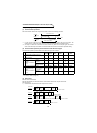
9
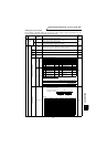
All parameter
clear
HFC
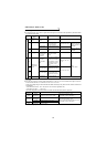
All parameters return to the factory settings.
Any of four different clear operations is performed according to the data.
When all parameter clear is executed for H9696 or H9966, communication-
related parameter settings also return to the factory settings. When resuming
operation, set the parameters again.
*Pr. 75 is not cleared.
4 digits
10
Parameter
write
H80 to HFD
Refer to the instruction code list (page 213) and write and/or read parameter
values as required.
When setting Pr. 100 and later, link parameter extended setting must be set.
4 digits
11
Parameter
read
H00 to H7B
12
Link
parameter
expansion
setting
Read
H7F
Parameter description is changed according to H00 to H09 setting. For
details of the settings, refer to the parameter instruction code list (page 213).
2 digits
Write
HFF
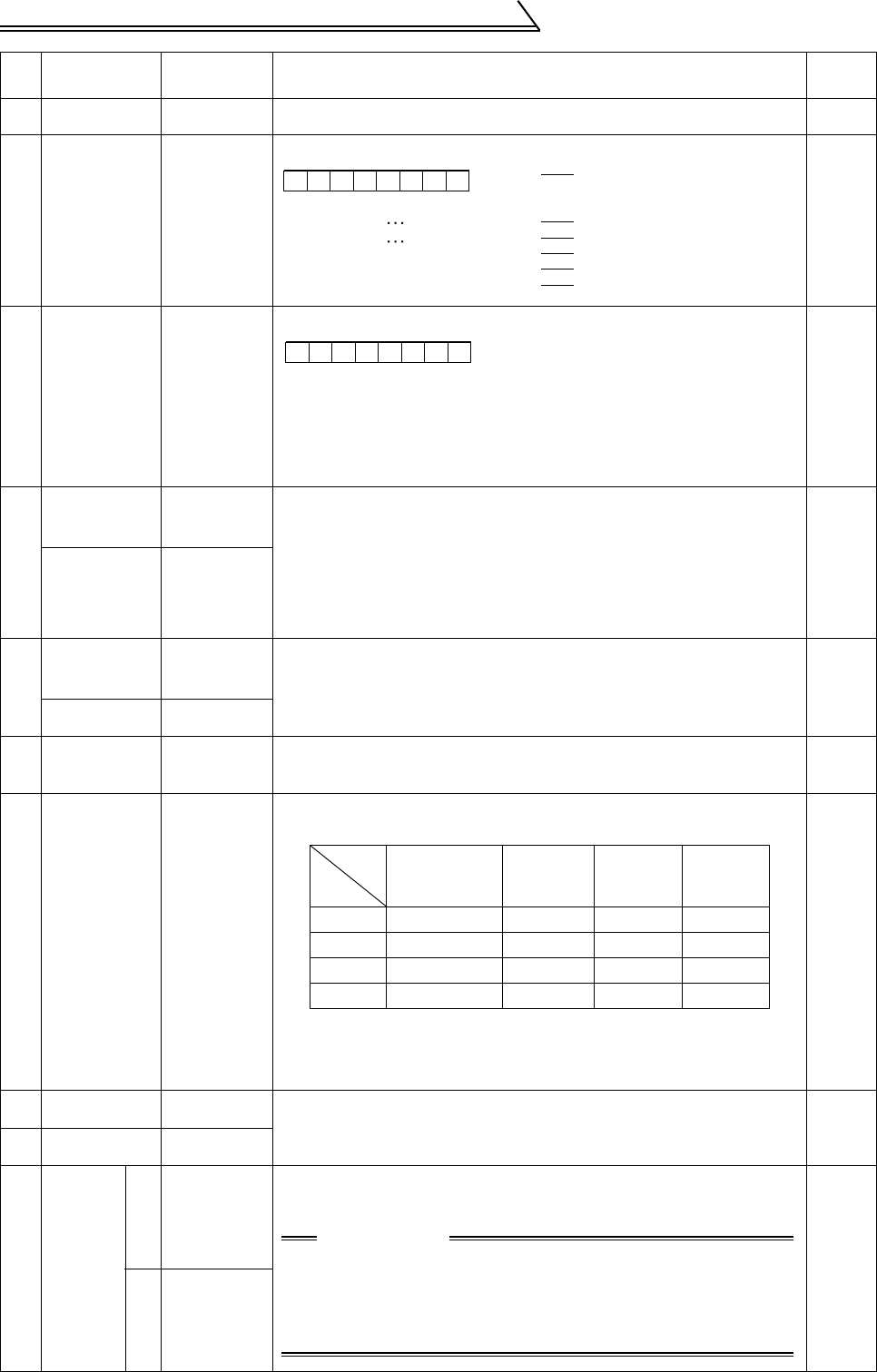
No. Item
Instruction
Code
Description
Number
of Data
Digits
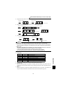
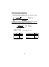
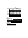
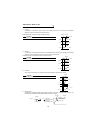
00000010
b7 b0
(For example 1)
[Example 1] H02 Forward rotation
[Example 2] H00 Stop
b0:
b1: Forward rotation (STF)
b2: Reverse rotation (STR)
b3:
b4:
b5:
b6:
b7:
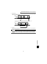
00000010
b7 b0
(For example 1)
[Example 1] H02
[Example 2] H80
b0: Inverter running (RUN)
b1: Forward rotation
b2: Reverse rotation
b3: DO1*
b4: DO2*
b5: DO3*
b6: Speed detection (FB)
b7: Alarm occurrence*
······
······
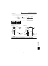
During forward
rotation
Stop due to
alarm occurrence
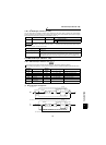
Pr.
Communication
Pr.
Calibration
Pr.
Other Pr. *
HEC
HF3
HFF
Data
H9696
{
×
{{
H9966
{{{{
H5A5A ××
{{
H55AA ×
{{{
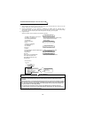
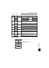
CAUTION
When the instruction code "HFF" was rewritten, increments
of the speed monitor, write and read is changed.
HFF = "0" . . . . . . . . . . . . .1r/min increments
HFF = "1" . . . . . . . . . . . . .0.1r/min increments
HFF = more than "2" . . . .1r/min increments