


7
Connection of stand-alone option units
WIRING
1
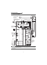
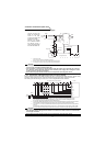
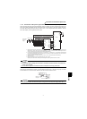
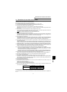
1.3.5 Connection of the power regeneration common converter (FR-CV)
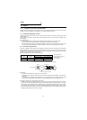
When connecting the FR-CV type power regeneration common converter, connect the inverter terminals (P, N) and
FR-CV type power regeneration common converter terminals as shown below so that their symbols match with
each other. After making sure that the wiring is correct, set "2" in Pr. 30 "regenerative function selection". Use the
FR-CV with capacity one rank greater than the inverter.
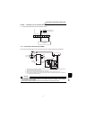
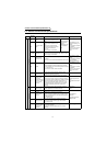
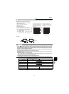
1.3.6 Connection of the DC reactor (FR-HEL/BEL)
When using the FR-HEL/BEL DC reactor, connect it between terminals P1-P. In this case, the jumper connected
across terminals P1-P must be removed. Otherwise, the reactor will not exhibit its function.
*1 Remove the jumpers across terminals R-R1 and S-S1 of the inverter, and connect the control circuit power supply across
terminals R1-S1. Always keep the power input terminals R, S, T open. Incorrect connection will damage the inverter.
(E.OPT (option alarm) will occur. (Refer to the Instruction Manual (basic).))
*2 Do not insert an MCCB between the terminals P − N (between P/L+ − P, between N/L- − N). Connect the inverter terminals
(P, N) and power regeneration common converter (FR-CV) terminals so that their terminal signals match with each other.
(Incorrect connection will damage the inverter.).
*3 Assign the terminal for X10 signal using any of Pr. 180 to Pr. 183. Pr.187 (input terminal function selection).
(Refer to page 150)
*4 Be sure to connect the power supply and terminals R/L11, S/L21, T/MC1.
Operating the inverter without connecting them will damage the power regeneration common converter.
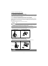
CAUTION
1. The voltage phases of terminals R/L11, S/L21, T/MC1 and terminals R2/L1, S2/L2, T2/L3 must be
matched.
2. Use sink logic (factory setting) when the FR-CV is connected. The FR-CV cannot be connected when
source logic is selected.
3. Do not remove a jumper across terminal P and P1 except when connecting a DC reactor.
CAUTION
1. The wiring distance should be within 5m.
2. The size of the cables used should be equal to or larger than that of the power supply cables (R, S, T).
MC
1
MCCB
R/L
11
Dedicated stand-alone
reactor (FR-CVL)
S/L
21
T/L
31
R2/L
12
S2/L
22
T2/L
32
R2/L
1
S2/L
2
T2/L
3
R/L
11
S/L
21
T/MC1
P/L+
N/L-
U
V
W
IM
Three-phase
A
C power
supply
FR-CV power regeneration
common converter
Inverter
PC
SD
X10 *3
RES
P24
SD
RDYB
RSO
SE
RDYA
*4
*2
R
S
T
R1
S1
P
N
*1
P1
FR-HEL/BEL
Remove
the jumper.
P