


133
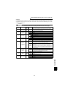
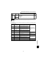
Communication functions (Pr. 117 to Pr. 124, Pr. 342)
PARAMETERS
3
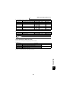
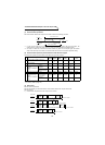
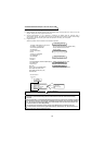
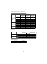
7) Sum check code
The sum check code is 2-digit ASCII (hexadecimal) representing the lower 1 byte (8 bits) of the sum (binary)
derived from the checked ASCII data.
8) Error code
If any error is found in the data received by the inverter, its definition is sent back to the computer together with
the NAK code. (Refer to page 137.)
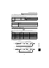
CAUTION
1. When the data from the computer has an error, the inverter does not accept that data.
2. All data communication, e.g. run command or monitoring, are started when the computer gives a
communication request. The inverter does not return any data without the computer's request. For
monitoring, etc. therefore, design the program to cause the computer to provide a data read request
as required.
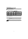
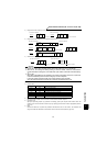
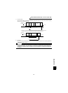
(Example 1)
Computer Inverter
ENQ
Waiting
time
1
Instruction
code
Station
number
0
1
Data
Sum check
code
E1 07ADF4
H05 H30 H31 H31H45 H31 H30 H37 H41 H44 H46 H34
H
= 1F4
Sum
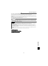
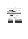
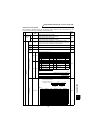
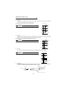
(Example 2)
Inverter Computer
STX Read data
0 117 0 30
H02 H30 H31 H37H31 H37 H30 H03 H33 H30
Binary code
H
= 130
Sum
ETX
7
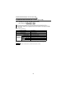
: When the Pr. 123 "waiting time setting" setting is other than 9999, create the communication request
data without "waiting time" in the data format. (The number of characters decreases by 1.)
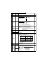
H
30
H
31
H
45
H
31
H
31
H
30
H
37
H
41
H
44
++++++++
ASCII code
Sum check
code
H
30
H
31
H
31
H
37
H
37
H
30
+++++
Station
number
ASCII code
Binary code
*
*