


207
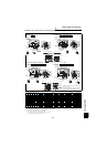
Outline dimension drawings
SPECIFICATIONS
4
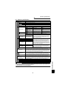
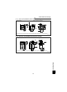
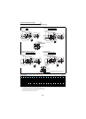
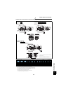
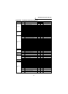
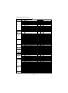
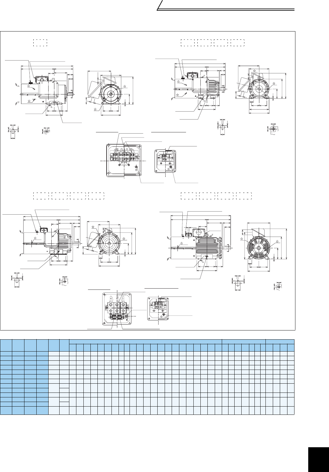
Dedicated motor outline dimension drawings (standard horizontal type with brake)
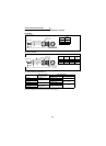
Dimensions table (Unit: mm)
Note)1. Install the motor on the floor and use it with the shaft horizontal.
2.
Leave an enough clearance between the fan suction port and wall to ensure adequate cooling.
Also, check that the ventilation direction of a fan is from the opposite load side to the load side.
3. The size difference of top and bottom of the shaft center height is .
4. The 400V class motor has -H at the end of its type name.
5. Since a brake power device is a stand-alone, install it inside the enclosure.
(This device should be arranged at the customer side.)
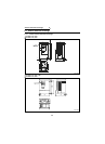
Frame Number 90L
SF-V5RU(H)
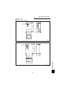
Frame Number 100L, 112M, 132S, 132M
SF-V5RU(H) , , ,
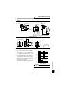
Frame Number 160M, 160L, 180M, 180L
SF-V5RU(H) , , ,
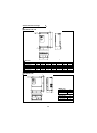
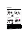
Frame Number 200L, 225S
SF-V5RU(H) , , ,
SF-V5RU
KB
(kW)
SF-V5RU
KB1
(kW)
SF-V5RU
KB3
(kW)
SF-V5RU
KB4
(kW)
Frame
No.
Mass
(kg)
Motor Shaft End
Terminal Screw Size
A B C D E F G H I J KA KD KG KL KP L M ML N X XB Z Q QK R S T U W
U,V,W
A,B,(C)
G1,G2 B1,B2
1 — — —
90L
29
296.5
114 90
183.6
70
62.5
4 — — — 53 27 65 220 245 465 175 — 150 15 56 9 50 40
168.5
24j6
7 4 8 M6 M4 M4 M4
2 1 — —
100L
46
333.5
128 100 207 80 70 6.5 — — 40 65 27 78 231 265
526.5
200 212 180 4 63 12 60 45 193
28j6
7 4 8 M6 M4 M4 M4
3 2 1 —
112M
53 355 135 112 228 95 70 6.5 — — 40 69 27 93 242 290 555 230 242 180 4 70 12 60 45 200
28j6
7 4 8 M6 M4 M4 M4
5 3 2 —
132S
70 416 152 132 266 108 70 6.5 — — 40 75 27 117 256 329 655 256 268 180 4 89 12 80 63 239
38k6
8 5 10 M6 M4 M4 M4
7 5 3 1
132M
80 435 171 132 266 108 89 6.5 — — 40 94 27 117 256 329 693 256 268 218 4 89 12 80 63 258
38k6
8 5 10 M6 M4 M4 M4
11 7 5 2
160M
140
522.5
198 160 318 127 105 8 — — 50 105 56 115 330 391
845.5
310 — 254 4 108 14.5 110 90 323
42k6
8 5 12 M8 M4 M4 M4
15 11 7 3
160L
155
544.5
220 160 318 127 127 8 — — 50 127 56 115 330 391
889.5
310 — 298 4 108 14.5 110 90 345
42k6
8 5 12 M8 M4 M4 M4
18 — — —
180M
185
568.5 225.5
180 363
139.5 120.5
8 — — 50 127 56 139 352 428 920 335 — 285 4 121 14.5 110 90
351.5
48k6
9 5.5 14 M8 M4 M4 M4
22 15 11 — 215
— 18 15 5
180L
255
587.5 242.5
180 363
139.5 139.5
8 — — 50 146 56 139 352 428 958 335 — 323 4 121 14.5 110 90
370.5
55m6
10 6 16 M8 M4 M4 M4
30 — — 7
200L
305
644.5 267.5
200 406 159
152.5
11 — — 70 145 90 487 — 546
1070
390 — 361 4 133 18.5
14
0
110
425.5
60m6
11 7 18
M10
M4 M4 M4
30, 45 22, 30 18, 22 — 330
55 37 30 11, 15
225S
395 659 277 225 446 178 143 11 — — 70 145 90 533 — 592
1091
428 — 342 4 149 18.5
14
0
110 432
65m6
11 7 18
M10
M4 M4 M4
1KB 2KB 3KB 5KB 7KB
Sliding distance
Frame leg viewed
from above
Z
X
Section AA
U
W
T
S
Connector (for encoder)
MS3102A20-29P
Mark for earthing
(grounding)
Earth (ground)
terminal (M5)
A
A
R
B
N
F F
XB
50
40
Suction
Exhaust
Direction of
cooling fan wind
Terminal box for cooling fan
L
A
KA
M
E E
C
G
D
φ22
2
2
1
1
KL
KP
KG
φ27
Main
terminal box
Connector (for encoder)
MS3102A20-29P
Earth (ground)
terminal (M5)
Mark for earthing
(grounding)
Suction
Exhaust
Direction of
cooling fan wind
A
A
R
N
F F XB
C
G
D
ML
M
E E
J
B Q
QK
Main
terminal box
A
L
Terminal box for cooling fan
φ22
φ27
KA
KL
KP
H
KG
Section AA
W
S
U
T
Sliding distance
Frame leg viewed
from above
Z
X
1
2
1
2
VU
B2B1
W
G1 G2
CBA
For motor (U, V, W)
For cooling fan (A, B)
For brake (B1, B2)
For thermal protector (G1, G2)
Earthing (grounding)
terminal (M4)
Main terminal box
Earthing (grounding)
terminal (M4)
Terminal box for cooling fan
11KB 15KB 18KB 22KB 30KB 37KB 45KB 55KB
Sliding distance
Frame leg viewed
from above
X
Z
W
S
U
T
Section AA
Connector (for encoder)
MS3102A20-29P
Earth (ground)
terminal (M8)
Mark for earthing
(grounding)
Suction
Direction of
cooling fan wind
Terminal box for cooling fan
1, 2
1
2
A
A
R
B
110
KA
Exhaust
90
N
F F
XB
L
A
H
C
G
D
M
E
E
J
KG
φ56
φ22
KL
KP
Main
terminal box
Sliding distance
Z
X
Frame leg viewed
from above
Section AA
U
T
W
S
Connector (for encoder)
MS3102A20-29P
Earth (ground)
terminal (M12)
Mark for earthing
(grounding)
1
2
D
H
C
G
M
E E
J
φ90
KP
KG
A
A
R
B
140
KA
110
N
F F
XB
Suction
Exhaust
Direction of
cooling fan wind
L
A
Terminal box for cooling fan
1, 2
φ22
Main
terminal box
For cooling fan (A, B, C)
For motor (U, V, W)
Earthing
(grounding)
terminal (M8)
Earthing (grounding)
terminal (M4)
For brake (B1, B2)
For thermal protector (G1, G2)
Main terminal box
Terminal box for cooling fan
indicates an inserting position of a bolt with hex head
holes for manual opening.
Make sure to earth the earth terminal of the frame installation
foot as well as the earth terminal in the terminal box.
0
-0.5