


WIRING
1
17
Others
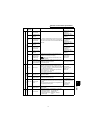
1.6.5 Inverter-generated noises and their reduction techniques
Some noises enter the inverter to malfunction it and others are radiated by the inverter to malfunction peripheral
devices. Though the inverter is designed to be insusceptible to noises, it handles low-level signals, so it requires the
following basic techniques. Also, since the inverter chops outputs at high carrier frequency, that could generate
noises. If these noises cause peripheral devices to malfunction, measures should be taken to suppress noises.
These techniques differ slightly depending on noise propagation paths.
1) Basic techniques
• Do not run the power cables (I/O cables) and signal cables of the inverter in parallel with each other and do
not bundle them.
• Use twisted pair shielded cables for the detector connection and control signal cables, and connect the
sheathes of the shield cables to terminal SD.
• Earth (Ground) the inverter, motor, etc. at one point.
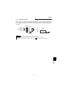
2) Techniques to reduce noises that enter and malfunction the inverter
When devices that generate many noises (which use magnetic contactors, magnetic brakes, many relays, for
example) are installed near the inverter and the inverter may be malfunctioned by noises, the following
measures must be taken:
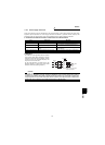
•Provide surge suppressors for devices that generate many noises to suppress noises.
•Fit data line filters (page 18) to signal cables.
•Earth (Ground) the shields of the detector connection and control signal cables with cable clamp metal.
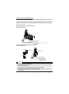
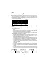
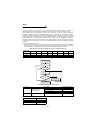
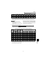
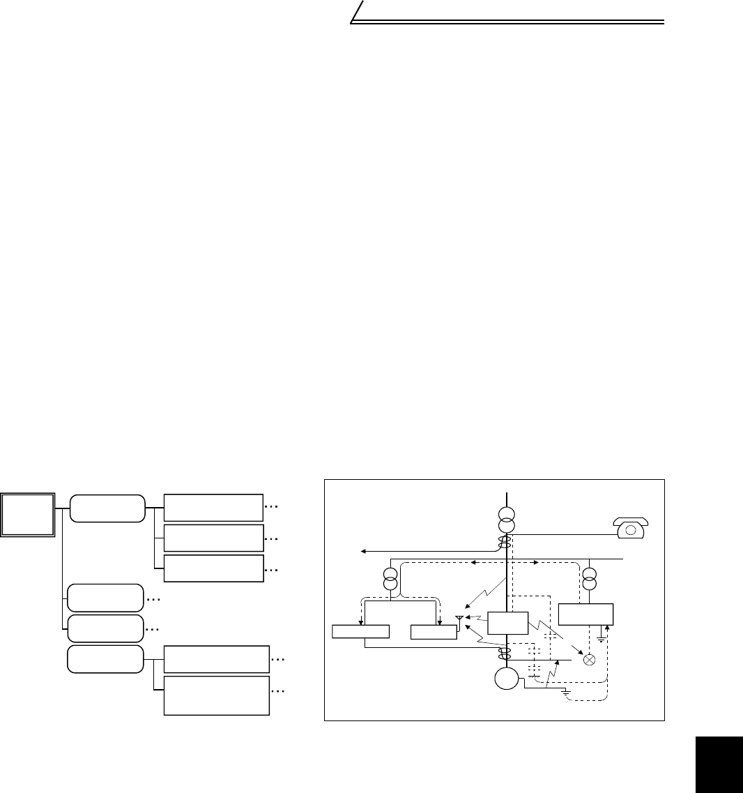
3) Techniques to reduce noises that are radiated by the inverter to malfunction peripheral devices
Inverter-generated noises are largely classified into those radiated by the cables connected to the inverter and
inverter main circuits (I/O), those electromagnetically and electrostatically induced to the signal cables of the
peripheral devices close to the main circuit power supply, and those transmitted through the power supply
cables.
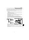
• By decreasing the carrier frequency, the mains terminal interface voltage* can be reduced. When motor noise
does not pose a problem, set the carrier frequency to a low value using Pr. 72.
(*Mains terminal interface voltage represents the magnitude of noise propagated from the inverter to the power
supply side.)
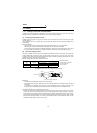
• Using shield cables as signal cables, induction noise can be reduced greatly (to 1/10 - 1/100). Induction noise
can also be reduced by separating the signal cables from the inverter output cables. (Separation of 30cm
reduces noise to 1/2-1/3.)
By fitting the FR-BSF01 or BLF on the inverter output side, induction noise to the signal cables can be reduced.
Path 4, 5
Air-propagated
noises
Path 6
Cable-propa-
gated noises
Magnetic
induction noises
Static induction
noises
noise
Inverter-
generated
Path 8
Noises directly
radiated by inverter
Noises radiated
by power cables
Noises radiated
by motor cables
Noises propagated
through power cables
Path 1
Path 2
Path 3
Path 7
Noise from earth
(Ground) cable due to
leakage current
IM
Telephone
5)
7)
7)
2)
1)
3)
6)
4)
Motor
Sensor
8)
Sensor
power supply
Receiver
Instrument
Inverter
1)
3)