


61
Position control (Pr. 419 to Pr. 430,
Pr. 464 to Pr. 494)
VECTOR CONTROL
2
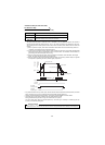
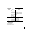
<Relationship between position resolution Δ and overall accuracy>
Since overall accuracy (positioning accuracy of machine) is the sum of electrical error and mechanical error,
normally take measures to prevent the electrical system error from affecting the overall error. As a guideline, refer to
the following relationship.
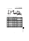
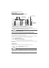
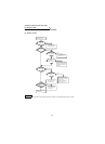
<Stopping characteristic of motor>
When parameters are used to run the motor, the command pulse frequency and motor speed have the relationship
as shown in the chart on page 58, and as the motor speed decreases, pulses are accumulated in the deviation
counter of the inverter. These pulses are called droop pulses (
ε) and the relationship between command frequency
(fo) and position loop gain (Kp: Pr. 422) is as represented by the following expression.
When the factory setting of Kp is 25s
-1
, the droop pulses (ε) are 8192 pulses.
Since the inverter has droop pulses during running, a stop settling time (ts) is needed from when the command has
zeroed until the motor stops. Set the operation pattern in consideration of the stop settling time.
When the factory setting of Kp is 25s
-1
, the stop settling time (ts) is 0.12s.
The positioning accuracy
Δ ε is (5 to 10) × Δ = Δ ε [mm]
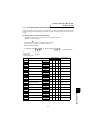
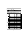
z Position command acceleration/deceleration time constant (Pr. 424)
1) When the electronic gear ratio is large (about 10 or more times) and the speed is low, rotation will not be
smooth, resulting in pulse-wise rotation. At such a time, set this parameter to smooth the rotation.
2) When acceleration/deceleration time cannot be provided for the command pulses, a sudden change in
command pulse frequency may cause an overshoot or error excess alarm. At such a time, set this parameter to
provide acceleration/deceleration time.
Normally set 0.
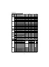
"Setting example 1"
The travel per pulse is
Δ = 0.01 (mm) in a drive system where the ballscrew pitch PB = 10 (mm) and the
reduction ratio 1/n = 1 and the electronic gear ratio is
Δs = 10 (mm) when the number of feedback pulses Pf =
4000 (pulse/rev). According to the following expression,
Therefore, set "4" in Pr. 420 and "1" in Pr. 421.
"Setting example 2"
Find the internal command pulse frequency of the dedicated motor rated speed.
Note that the command pulse scaling factor Pr. 420/Pr. 421 = 1.
Assuming that the number of encoder pulses is 2048 (pulses/rev) (feedback pulse Pf = 2048 × 4),
Therefore, the internal command pulse frequency is 204800 (pps).
Pf
Pr. 420
Pr. 421
Pf
Pr. 420
Pr. 421
0.01
4000
10
4
1
60
No
2048
Pr. 421
Pr. 420
fo
204800
4
5
1
10
1
: Positioning accurac
y
to
fo
Kp
[pulse]
204800
25
[pulse] (motor rated speed)
ts
1
Kp
[s]
3