114
Operation selection function 2 (Pr. 65 to Pr. 79)
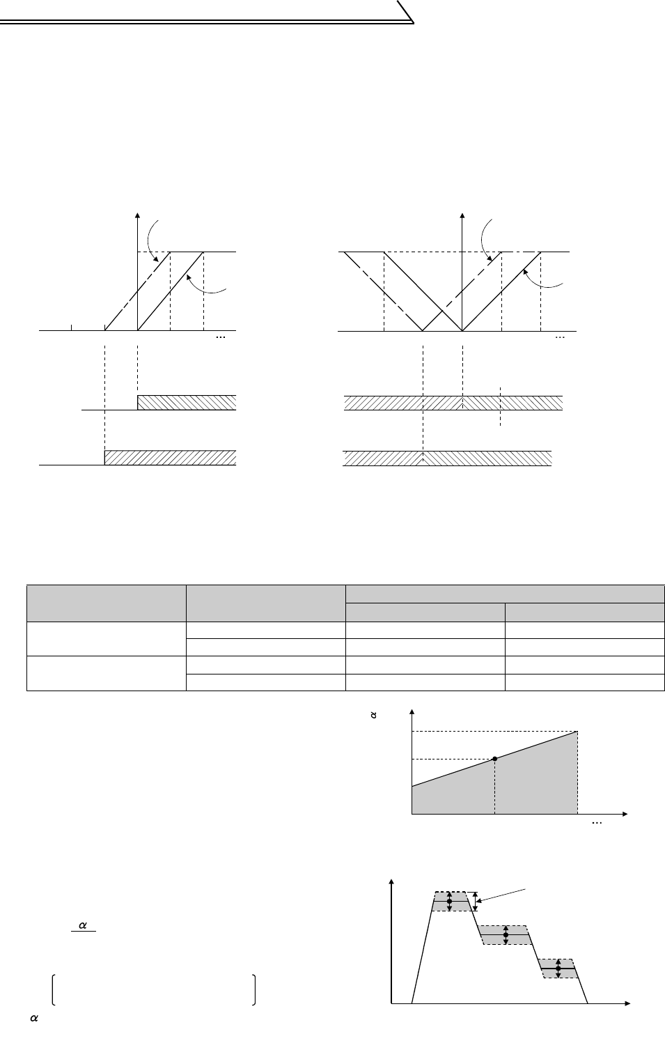
(a) When Pr. 73 "speed setting signal" value is "0"
The voltage across terminals 1-5 is added to the voltage signal (positive) across terminals 2-5. If the result of
addition is negative, it is regarded as 0 and the motor comes to a stop.
(b) When Pr. 73 "speed setting signal" value is "10"
The polarity reversible operation function is selected.
The voltage signal across terminals 1-5 is added to the voltage signal (positive) across terminals 2-5. A positive
addition result turns the motor in the forward rotation direction (when the STF terminal turns on), or a negative
result turns it in the reverse rotation direction (when the STF terminal turns on). The compensation signal of
terminal 1 can also be added to the multi-speed setting.
Auxiliary Input Characteristics
1) Multi-speed input compensation
By setting 1 in Pr. 28 "multi-speed input compensation selection" (factory setting 0), the speed from the
auxiliary input terminal 1 is added when multi-speed operation is performed. (Refer to page 77.)
Inverter Output According to Start Signal and Auxiliary Input Terminal Polarity
Pr. 73 Setting
Added Command
Voltage
Start Signal Input
STF-SD STR-SD
0
+ Forward rotation Reverse rotation
− Stop Stop
10
+ Forward rotation Reverse rotation
− Reverse rotation Forward rotation
2) Override
For the above compensation input, the fixed
compensation amount is applied to each speed.
Using the override function easily varies each speed
equally.
By setting either "4 or 14" in Pr. 73, override allows the
parameter-set multiple speeds and analog input
across terminals 1-5 to be varied equally within the
range 50% to 150% (The range can be increased with
Pr. 252 and Pr. 253) by the analog signal input across
terminals 2-5.
How to find each speed (N)
Override Setting Signal vs. Compensation Amount
Multi-speed Override Operation
Output speed
When voltage
across terminals
2-5 is 5V
When voltage
across terminals
2-5 is 0V
+10V
Terminal 1
0
-5V-10V
Forward
rotation
Forward
rotation
(a) When Pr. 73 setting is 0
+5V
+10V
0
-5V-10V
When
STF-SD
is on
(b) When Pr. 73 setting is 10
Reverse
rotation
+5V
Terminal 1
When voltage
across terminals
2-5 is 5V
When voltage
across terminals
2-5 is 0V
Output speed
hen
STF-SD
is on
Reverse
rotation
Forward
rotation
Forward
rotation
N = Npr. ×
100
Npr.: Speed setting [r/min]
[r/min]
Multiple speeds
Analog input across terminals 1-5
: Override compensation amount [%]
(Analog input across terminals 2-5)
10V
150%
100%
50%
0
5
Compensation amount
Terminal 2
High
speed
Middle
speed
Low
speed
Compensation range
by override
Time
Output
speed
(r/min)


