


31
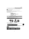
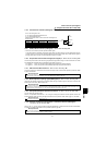
How to use the input signals
(assigned terminals DI1 to DI4, STR)
WIRING
1
1.8.4 Third function selection (X9 signal): Pr. 180 to Pr. 183, Pr. 187 setting "9"
1.8.5 FR-HC, FR-CV connection (X10 signal): Pr. 180 to Pr. 183, Pr. 187 setting "10"
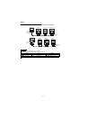
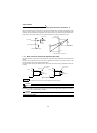
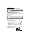
• FR-HC, FR-CV connection (inverter operation enable signal)
To provide protective coordination with the high power factor converter (FR-HC) or power regeneration common
converter (FR-CV), use the inverter operation enable signal to shut off the inverter output. Enter the RDY signal of
the high power factor converter or power regeneration common converter.
1.8.6
PU operation external interlock signal (X12 signal):
P
r. 180 to Pr. 183, Pr. 187 setting "12"
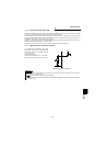
This function prevents the inverter from being inoperative during operation using an external command if the mode
is accidentally left unswitched from PU operation mode. (Refer to page 115.)
X12 signal on ..... Shift to PU operation mode enabled (output stop during external operation)
X12 signal off ..... Shift to PU operation mode disabled (output stop during external operation)
1.8.7 PID control enable terminal: Pr. 180 to Pr. 183, Pr. 187 setting "14"
Turn the X14 signal on to exercise PID control. When this signal is off, normal inverter operation is performed. Refer
to page 139 for details.
1.8.8 Brake sequence opening signal (BRI signal): Pr. 180 to Pr. 183, Pr. 187 setting "15"
Used when the method of inputting the mechanical brake opening completion signal to the inverter is used for the
brake sequence functions. (Refer to page 106.)
1.8.9 PU operation/external operation switchover: Pr. 180 to Pr. 183, Pr. 187 setting "16"
You can change the operation mode.
When Pr. 79 "operation mode selection" = "8", turning the X16 signal on shifts the current operation mode to the
external operation mode and turning that signal off shifts to the PU operation mode. Refer to page 117 for details.
1.8.10 S-pattern acceleration/deceleration C switchover terminal (X20 signal)
: Pr. 180 to Pr. 183, Pr. 187 setting "20"
When Pr. 29 = "4", you can use the S-pattern acceleration/deceleration C switchover terminal to set the acceleration
of S-pattern acceleration/deceleration in the parameter. (Refer to page 89.)
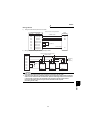
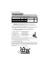
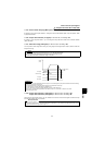
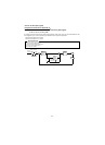
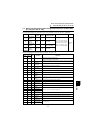
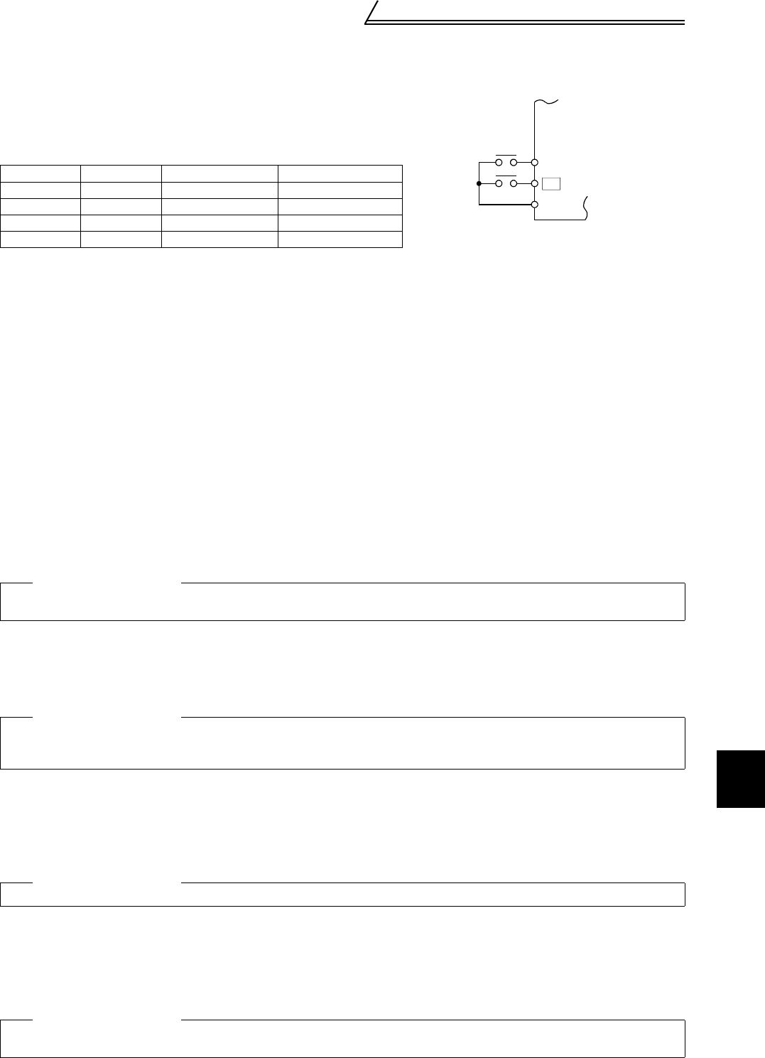
Turn on this "X9 signal" to set:
Pr. 110 "third acceleration/deceleration time"
Pr. 111 "third deceleration time"
Select either the first motor or the second motor according to the
RT signal input.
X9 signal RT signal Applied Motor Other Function
OFF OFF First motor First function
OFF ON Second motor Second function
ON OFF First motor Third function
ON ON Second motor Third function
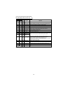
Related parameters
Pr. 128 "PID action selection", Pr. 129 "PID proportional band", Pr. 130 "PID integral time", Pr. 131 "upper limit", Pr. 132 "lower limit",
Pr. 133 "PID action set point for PU operation", Pr. 134 "PID differential time" (Refer to page 139.)
Related parameters
Pr. 60 "intelligent mode selection", Pr. 278 "brake opening speed", Pr. 279 "brake opening current", Pr. 280 "brake opening current
detection time", Pr. 281 "brake operation time at start", Pr. 282 "brake operation speed", Pr. 283 "brake operation time at stop", Pr. 284
"deceleration detection function selection", Pr. 285 "overspeed detection speed" (Refer to page 106.)
Related parameters
Pr. 79 "operation mode selection" (Refer to page 117)
Related parameters
Pr. 29 "acceleration/deceleration pattern", Pr. 380 "acceleration S pattern 1", Pr. 381 "deceleration S pattern 1", Pr. 382 "acceleration
S pattern 2", Pr. 383 "deceleration S pattern 2" (Refer to page 89.)
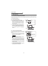
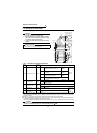
STF(STR)
SD
Inverter
Start
Third acc/dec
X9