


135
Communication functions (Pr. 117 to Pr. 124, Pr. 342)
PARAMETERS
3
<Setting items and set data>
After completion of parameter setting, set the instruction codes and data and start communication from the
computer to allow various types of operation control and monitoring.
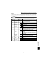
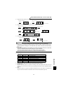
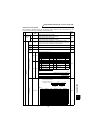
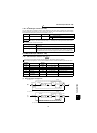
No. Item
Instruction
Code
Description
Number
of Data
Digits
1
Operation
mode
Read
H7B
H0000: Communication option operation
H0001: External operation
H0002: Communication operation (PU connector)
4 digits
Write
HFB
H0000: Communication option operation
H0001: External operation
H0002: Communication operation (PU connector)
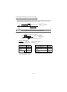
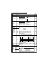
2
Monitoring
Speed H6F
H0000 to HFFFF: Speed (hexadecimal) in 1r/min increments (4 digits)
[In 0.1r/min increments (6 digits) when HFF = 1.]
When the Pr.37 and Pr.144 settings are changed to display items other than
motor speed, values will not be read in 0.1r/min increments.
4 digits
(6 digits)
Output
current
H70 H0000 to HFFFF: Output current (hexadecimal) in 0.01A increments 4 digits
Output
voltage
H71 H0000 to HFFFF: Output voltage (hexadecimal) in 0.1V increments 4 digits
Special
monitor
H72 H0000 to HFFFF: Monitor data selected in instruction code HF3 4 digits
Special monitor selection No.
Read H73
2 digits
Write HF3
Alarm definition
H74 to H77
H0000 to HFFFF: Two latest alarm definitions
Alarm definition display example (instruction code H74)
Alarm data
4 digits
H01 to H0E: Monitor selection data
*0.1r/min increments when HFF = 1
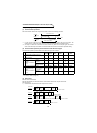
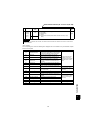
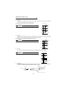
<Input terminal monitor details>
<Output terminal monitor details>
Data Description
Increments
Data Description
Increments
H01 Output frequency 0.01Hz H10 Output terminal status —
H02 Output current 0.01A H11 Load meter 0.1%
H03 Output voltage 0.1V H12 Motor excitation current 0.01A
H05 Speed setting* 1r/min H13 Position pulse —
H06 Running speed* 1r/min H14
Cumulative energization
time
1h
H07 Motor torque 0.1% H17 Actual operation time 1h
H08
Converter output
voltage
0.1V H18 Motor load factor 0.1%
H09 Regenerative brake 0.1% H20 Torque command 0.1%
H0A
Electronic overcurrent
protection load factor
0.1% H21 Torque current command 0.1%
H0B
Output current peak
value
0.01A H22 Motor output 0.01kW
H0C
Converter output
voltage peak value
0.1V H23 Feedback pulse —
H0F Input terminal status —
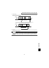
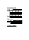
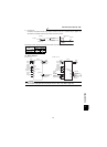
b15 b0
RES OH DI4 DI3 DI2 DI1 STR STF
b15 b0
ABCDO3DO2DO1
Read data: [Example] H30A0
(Previous alarm THT)
(Latest alarm OPT)
0101000000 000011
b15 b8b7 b0
Latest alarm
(HA0)
Previous alarm
(H30)
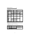
Data Description Data Description Data Description
H00 No alarm H81 LF HD3 OD
H10 OC1 H90 OHT HD4 ECA
H11 OC2 HA0 OPT HD5 MB1
H12 OC3 HA1 OP1 HD6 MB2
H20 OV1 HA2 OP2 HD7 MB3
H21 OV2 HA3 OP3 HD8 MB4
H22 OV3 HB0 PE HD9 MB5
H30 THT HB1 PUE HDA MB6
H31 THM HB2 RET HDB MB7
H40 FIN HC1 CTE HDC EP
H50 IPF HC2 P24 HF1 E.1
H51 UVT HC3 P12 HF2 E.2
H60 OLT HD0 OS HF3 E.3
H70 BE HD1 OSD HF6 E.6
H80 GF HD2 ECT HF7 E.7