


2
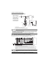
Internal block diagram
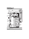
1.1 Internal block diagram
CAUTION
1. The 18.5K or more is not equipped with the built-in brake resistor and brake transistor marked *. The brake transistor is
provided for the 15K or less and the built-in brake resistor for the 5.5K or less.
2. Always earth (ground) the inverter and motor.
3. **: When using an external thermal relay protection, set "1" (external thermal relay valid) in Pr. 876. (factory setting)
(Refer to page 80.)
PBR
PAR
PZR
ASIC
RA
Protective
circuit
Control
power
supply
CHARGE
ASIC
DU04
-1
RS485
CPU
10V
PC
STF
STR
RES
DI1
DI2
DI3
SD
SINK
SOURCE
DI4
DO1
DO2
DO3
SE
A
B
C
DA1
DA2
OH
SD
PG
PA
PB
PZ
U
V
W
FR-V500
MCCB
MC
P1
PR
PX
3
1
10E
5
2
TA
TB
TZ
CMP
LDV
24V5.5V12V EXT
IM
Jumper: Remove this jumper when connecting
the FR-HEL/BEL.
Jumper: Remove this jumper when
connecting the FR-ABR.
(5.5K or less only)
Avoid frequent ON-OFF.
Repeated inrush current at power on
will shorten the converter life.
(switching life is about 100,000 times)
External transistor
common
Forward rotation
Reverse rotation
Reset
Multi-function
input 4
Four different
signals can be
selected using
the parameters.
Output speed
setting
potentiometer
Analog common
0 to 10VDC
0 to 10VDC
Three different
signals can be
selected using the
parameters.
(Open collector
output)
Alarm output
Jumper
U
V
W
R
TR
*
*
Change the jumper
connector and parameter
according to the encoder
specifications.
OPTION
#1
OPTION
#2
OPTION
#3
Analog
signal output
Encoder
Mitsubishi dedicated
motor (SF-V5RU)
FAN
MCCB MC
C
B
A
OCR
Verify the power specification
of the motor cooling fan when
performing wiring.
R
S
T
CAUTION
Match the phase
sequence. (The fan
should have intake
rotation.)
R
S
A
B
C
D
F
G
Thermal
protector
G2
G1
* *
PN
R
S
T
S1
R1
Refer to page 196.