


99
Display functions 1 (Pr. 52 to Pr. 56)
PARAMETERS
3
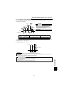
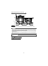
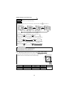
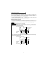
When "100" is set in Pr. 52, the monitored values during stop and during operation differ as indicated below. (The
LED on the left of r/min flickers during stop, and is lit during operation.)
When Pr. 52 = "100", the set speed displayed at a stop indicates speed to be output when the start command is on.
Different from the speed setting based on displayed when Pr. 52 = "5", the value maximum/minimum speed and
speed jump is displayed.
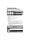
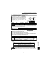
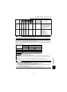
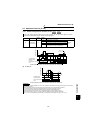
Torque
monitor
(driving/
regenerative
polarity
switchover)
*1
—— ××× 36 Pr. 866
The output torque is monitored.
When the DA1 output monitor is
used, a positive voltage is output
during forward and reverse driving
and a negative voltage is output
during forward and reverse
regeneration.
Trace
status
—— 38 38
×× × ——
The trace status is displayed.
0: Stop
1: During pre-trigger
2: Waiting for trigger
3: During trace
4: Trace completion
101: During data output
102: Data output completion
CAUTION
*1 When DA1 (Pr. 54) is selected, high responce output is available.
When DA2 (Pr. 158) is selected, average value is output.
*2 Select this monitor in "Others" of the FR-PU04V (option).
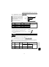
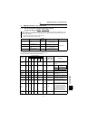
Pr. 52
0 100
During operation/
during stop
During stop During operation
Speed Speed Set speed Speed
Output current Output current
Output voltage Output voltage
Alarm display Alarm display
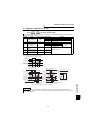
REMARKS
• During a reset, the values are the same as at a stop.
During offline auto tuning, the tuning status monitor has priority.
• By setting "0" in Pr. 52, the monitoring of output speed to alarm display can be selected in sequence by the SHIFT key.
• *Speed setting to output terminal status on the PU main monitor are selected by "other monitor selection" of the parameter
unit (FR-PU04V).
• When Pr. 52 = any of "17, 18 and 24", the output current monitor changes to the set monitored data.
When Pr. 52 = any of "19, 20, 23 and 32 to 35, 38", the output voltage monitor changes to the set monitored data.
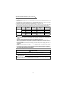
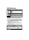
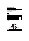
CAUTION
1. The cumulative energization time and actual operation time are accumulated from 0 to 65535 hours,
then cleared, and accumulated again from 0.
When the control panel (FR-DU04
-1) is used, more than 9999h is displayed as "– – – –".
Use the parameter unit (FR-PU04V) to confirm more than 9999h.
2. The cumulative energization time and actual operation time is not accumulated unless the inverter is
run continuously for more than one hour.
3. When the control panel (FR-DU04
-1) is used, the display unit is r/min, V or A only.
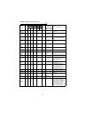
Signal
Type
Display
Unit
Parameter Settings
± Output
Full-Scale Value
of the Level
Meter Connected
to DA1 and DA2
Description
Pr. 52 Pr. 53 Pr. 54 Pr. 158
DU LED
PU main
monitor
PU level
meter
DA1
terminal
12 bits
(±10V)
DA2
terminal
12 bits
(+10V)