


WIRING
1
29
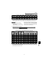
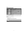
Input terminals
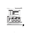
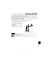
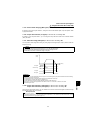
1.7.6 Common terminals (SD, 5, SE)
Terminals 5, SD and SE are common to the I/O signals and isolated from each other. Do not earth (ground) these
terminals. Avoid connecting the terminal SD and 5 and the terminal SE and 5.
Terminal SD is a common terminal for the contact input terminals (STF, STR, OH, RES, DI1, DI2, DI3 and DI4) and
the encoder output signals. When using the terminal SD as a common terminal for the encoder output signals, use
a shielded or twisted cable to protect it from external noise.
Terminal 5 is a common terminal for the speed setting analog input signals and analog output signals. Use a
shielded or twisted cable to protect it from external noise.
Terminal SE is a common terminal for the open collector output terminals (DO1, DO2, DO3).
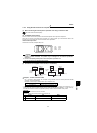
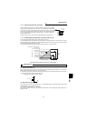
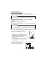
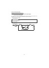
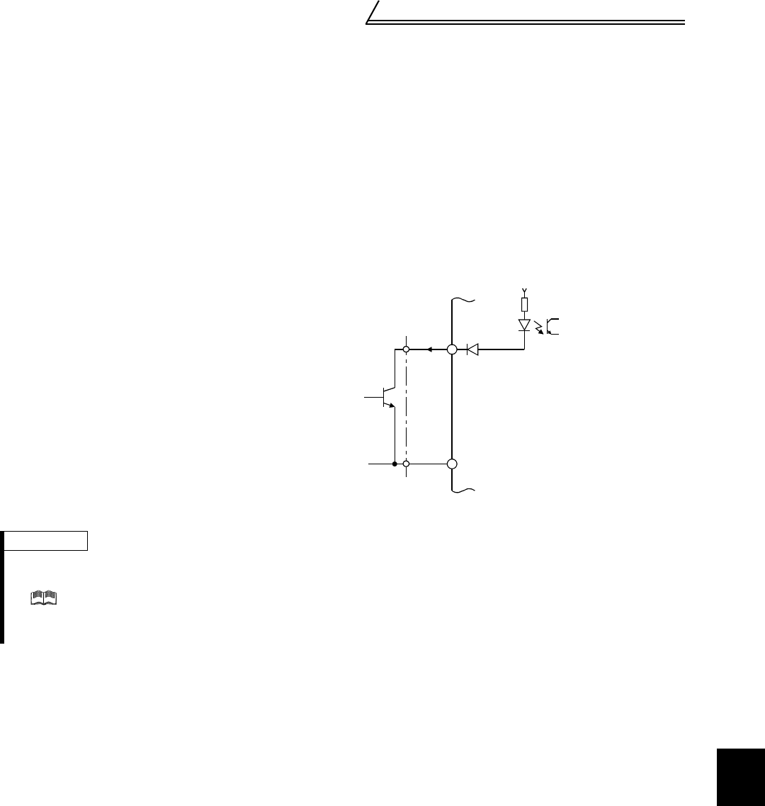
1.7.7 Signal inputs by contact-less switches
The contacted input terminals of the inverter
(STF, STR, RH, RM, AU) can be controlled using
a transistor instead of a contacted switch as
shown on the right.
Input resistance : 4.7kΩ
Voltage when contacts are open : 21 to 27VDC
When contacts are short-circuited : 4 to 6mADC
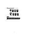
External Signal Input by Transistor
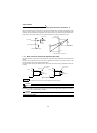
REMARKS
• When using an external transistor connected to the external power supply, use terminal PC to prevent a
malfunction due to a sneak current.
( Refer to the Instruction Manual (basic) for details.)
• Note that when off, an SSR (solid-state relay) has a relatively large leakage current and it may be accidentally
input to the inverter.
+24V
STF etc.
SD
Inverter