


98
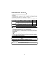
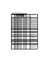
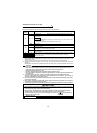
Display functions 1 (Pr. 52 to Pr. 56)
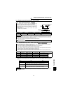
Regenerative
brake duty
0.1% 9 *2 9 9 × Pr. 70
The brake resistor duty is
displayed.
Electronic
overcurrent
protection
load factor
0.1% 10 *2 10 10
×
Thermal relay
operation level
The thermal relay load factor is
displayed.
Output
current
peak value
0.01A 11 *2 11 11
× Pr. 56
The peak value of the output
voltage is displayed as effective
value.
Converter
output
voltage
peak value
0.1V 12 *2 12 12
× 400V/800V
The peak value of DC bus voltage
is displayed.
Input
terminal
status
——
× *2 ×× × —— ————
Output
terminal
status
——
× *2 ×× × —— ————
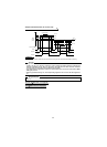
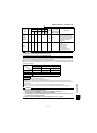
Load meter
*1
0.1% 17 17 17 17 Pr. 866 The load meter is output.
Motor
excitation
current
0.01A 18 18 18 18
× Pr. 56 Pre-excitation current is displayed.
Position
pulse
—— 19 19
×× × ——
The position of the motor output
shaft is monitored.
Cumulative
energization
time
1h 20 20 ×× × ——
Cumulative energization time since
the inverter shipment (power on
time) is displayed. (Minimum
increment is Hr)
Reference
voltage
output
—— ××× 21 × ——
The voltage of DA1 and DA2 at full-
scale is output
Actual
operation
time
1h 23 23
×× × ——
The inverter running time is
accumulated. (The time during a
stop is not accumulated.)
It is cleared using Pr. 171 "actual
operation hour meter clear".
Motor load
factor
0.1% 24 24
×× × ——
The load factor to the rated motor
capacity is displayed.
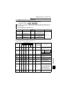
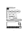
Torque
command*1
0.1% 32 32
× 32 Pr. 866
The torque command value is
displayed.
Torque
current
command*1
0.1% 33 33
× 33 Pr. 866
The torque current command value
is displayed.
Motor
output *1
0.01
kW
34 34
× 34
Rated motor
current
The machine output of the motor
shaft end is displayed.
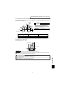
Feedback
pulse
—— 35 35
×× × ——
The number of pulses feed back
during 1 sampling is displayed.
Display range is 0 to 99999 pulses.
Sampling time for the following
number of encoder pulses are:
1.0s for 1500 pls/rev or less;
0.5s for 1501 to 3200 pls/rev; and
0.25s for 3201 to 4096 pls/rev.
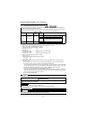
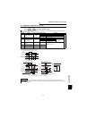
Signal
Type
Display
Unit
Parameter Settings
± Output
Full-Scale Value
of the Level
Meter Connected
to DA1 and DA2
Description
Pr. 52 Pr. 53 Pr. 54 Pr. 158
DU LED
PU main
monitor
PU level
meter
DA1
terminal
12 bits
(±10V)
DA2
terminal
12 bits
(+10V)