


146
Current detection (Pr. 150 to Pr. 153)
3.16 Current detection (Pr. 150 to Pr. 153)
3.16.1 Output current detection function (Pr. 150, Pr. 151 )
<Setting>
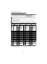
Refer to the following table and set the parameters.
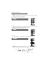
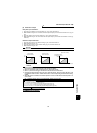
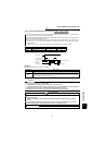
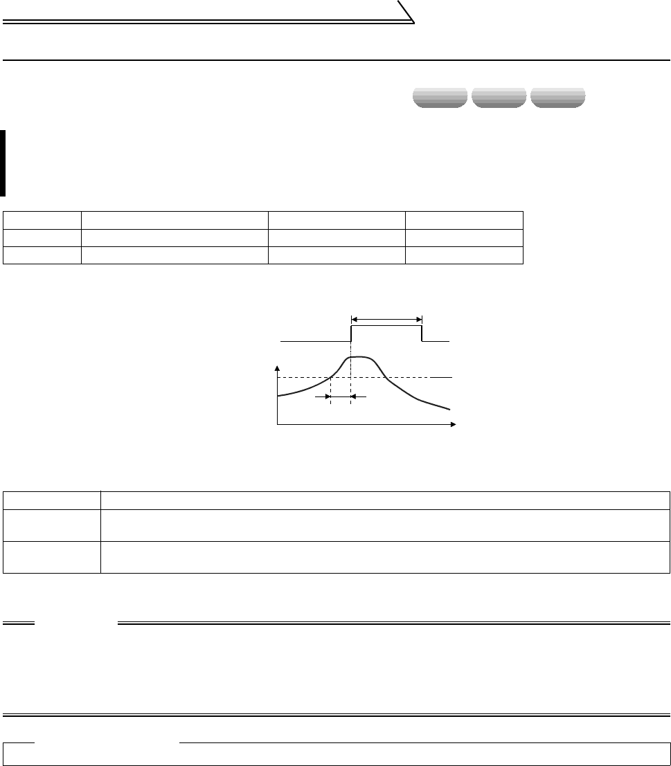
z If the output current remains higher than the Pr. 150 setting during inverter operation for longer than the
period set in Pr. 151, the output current detection signal (Y12) is output from the inverter's open collector
output terminal.
(Use any of Pr. 190 to Pr. 192 and Pr. 195 to assign the terminal used for Y12 signal output.)
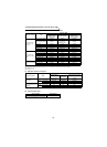
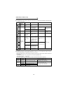
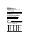
Parameter Name Factory Setting Setting Range
150 Output current detection level 150% 0 to 200.0%
151 Output current detection period 0 0 to 10s
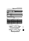
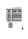
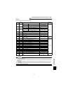
Parameter Description
150
Set the output current detection level.
100% is the rated inverter current.
151
Set the output current detection period. Set the period from when the output current has risen above the
setting until the output current detection signal (Y12) is output.
CAUTION
1. Once turned on, the output current detection signal is held on for at least 100ms.
2. This function is also valid during execution of the online or offline auto tuning.
3. Changing the terminal function using any of Pr. 190 to 192 and Pr. 195 may affect the other functions.
Confirm the functions of the corresponding terminals before making setting.
4. When "0" is set in Pr. 151, the output current detection period is about 50ms.
Related parameters
• Y12 signal terminal assignment ⇒ Pr. 190 to Pr. 192, Pr. 195 (output terminal function selection) (Refer to page 152.)
speed torque position
Time
Pr.151
Pr.150
OFF
ON
OFF
Output current
detection signal
Minimum 100ms
Output
current