


152
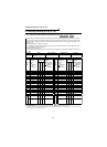
Terminal assignment functions (Pr. 180 to Pr. 195)
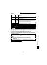
3.20.2 Output terminal function selection
(Pr. 190 to Pr. 192, Pr. 195 )
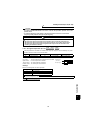
<Setting>
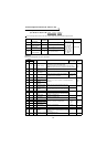
Refer to the following table and set the parameters.
You can change the functions of the open collector output terminal and contact output terminal.
Parameter Name
Factory-
Set Value
Factory-Set Signal Function Setting Range Remarks
190
DO1 terminal
function selection
0 RUN (Inverter running)
0 to 8, 10 to 16,
20, 25 to 27, 30
to 37, 39, 40 to
44, 96 to 99,
100 to 108, 110
to 116, 120, 125
to 127, 130 to
137, 139, 140 to
144, 196 to 199,
9999
Extended mode
191
DO2 terminal
function selection
1 SU (Up to speed)
192
DO3 terminal
function selection
2
IPF (Instantaneous power failure/
undervoltage)
195
ABC terminal
function selection
99 A, B, C (Alarm output)
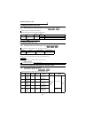
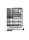
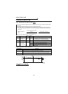
Setting
Signal
Name
Function Operation
Related
Parameters
Response
Time
Positive
logic
Negative
logic
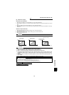
0 100 RUN Inverter running
This signal is output during operation when the inverter output
speed rises to or above the starting speed.
During DC injection brake, 0 speed control or servo lock, this
signal is not output. However, LX is output as ON under position
control.
Within
20ms
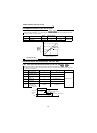
1 101 SU Up to speed Refer to Pr. 41 "up-to-speed sensitivity" (page 95). (Caution 1)
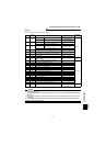
2 102 IPF
Instantaneous power
failure or
undervoltage
Output at occurrence of an instantaneous power
failure or undervoltage.
⎯
⎯
3 103 OL Overload alarm
Output when torque or speed limit is activated.
For V/F control, this signal is output while the stall
prevention function is activated.
Pr. 22, Pr. 806,
Pr. 807, Pr. 812
to Pr. 817
4 104 FU
Output speed
detection
Refer to Pr. 42, Pr. 43, Pr. 50 and Pr. 116 (speed detection)
(page 95).
Within
20ms
5 105 FU2
Second output speed
detection
6 106 FU3
Third output speed
detection
7 107 RBP
Regenerative brake
prealarm
Output when 85% of the regenerative brake duty
set in Pr. 70 is reached.
Pr. 70
⎯
8 108 THP
Electronic thermal
relay function
prealarm
Output when the electronic thermal relay function
cumulative value reaches 85% of the preset level.
Pr. 9
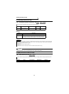
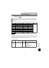
10 110 PU PU operation mode Output when the PU operation mode is selected.
⎯
Within
20ms
11 111 RY
Inverter operation
ready
Output when the inverter can be started by
switching the start signal on or while it is running.
12 112 Y12
Output current
detection
Refer to Pr. 150 and Pr. 151
(output current detection).
Pr. 150, Pr. 151
⎯
13 113 Y13
Zero current
detection
Refer to Pr. 152 and Pr. 153
(zero current detection).
Pr. 152, Pr. 153
14 114 FDN PID lower limit
Refer to Pr. 128 to Pr. 134 (PID control).
Pr. 128 to
Pr. 134
Within
20ms
15 115 FUP PID upper limit
16 116 RL
PID forward-reverse
rotation output
20 120 BOF
Brake opening
request
Refer to Pr. 278 to Pr. 285
(brake sequence function).
Pr. 278 to
Pr. 285
⎯
25 125 FAN Fan fault output Output at the time of a fan fault. Pr. 244 ⎯
26 126 FIN
Fin overheat
prealarm
Output when the heatsink temperature reaches
about 85% of the fin overheat protection activating
temperature.
⎯⎯
27 127 ORA Orientation in-position
When orientation is valid
(Refer to page 159)
⎯⎯
speed torque position