


57
Position control (Pr. 419 to Pr. 430,
Pr. 464 to Pr. 494)
VECTOR CONTROL
2
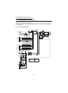
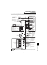
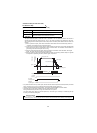
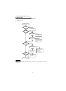
2.7.3 Control block diagram
2.7.4 Parameter
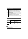
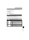
Set the following parameters when exercising position control with the inverter.
Parameter Name
Factory
Setting
Setting
Range
Description
Refer
To
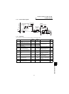
419
Position command source
selection
0 0, 1 Set position command input. 58
420
Command pulse scaling factor
numerator
1 0 to 32767
Set the electronic gear. 60
421
Command pulse scaling factor
denominator
1 0 to 32767
422 Position loop gain 25
0 to 150s
-1
Set the gain of the position loop. 62
423 Position feed forward gain 0% 0 to 100%
Function to cancel a delay
caused by the droop pulses of
the deviation counter.
62
424
Position command acceleration/
deceleration time constant
0s 0 to 50s 61
425
Position feed forward command
filter
0s 0 to 5s
Enter the primary delay filter in
response to the feed forward
command.
426 In-position width 100 pulses
0 to 32767
pulses
The in-position signal turns on
when the droop pulses become
less than the setting.
62
427 Excessive level error 40K
0 to 400K,
9999
An error becomes excessive
when the droop pulses exceed
the setting.
62
430 Pulse monitor selection 9999 0 to 5, 9999 Display the number of pulses. 62
464
Digital position control sudden
stop deceleration time
0 0 to 360.0s 60
RH
RM
RL
REX
STF
STR
Pr.4 to 6
Pr.24 to 27
Pr.232 to 239
Pr.465 to Pr.494
Travel
Multi-
speed
communication
2
Pr.419
Position command
source selection
0
Pr.420
Pr.421
Position command
acceleration/
deceleration
time constant
Pr.424
Position feed
forward
command filter
Pr.425
Command pulse selection
Pr.428
Electronic
gear
Positioning option
Command
pulse
Position feed
forward gain
Pr.423
Deviation
counter
Position
loop gain
Pr.422
IM
Speed
control
Differentiation
Clear signal
selection
Pr.429
(Pr.44, Pr.110)(Pr.45, Pr.111)
Pr.7 Pr.8
Encoder