


62
Position control (Pr. 419 to Pr. 430,
Pr. 464 to Pr. 494)
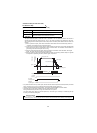
2.7.7 In-position width (Pr. 426)
The Y36 terminal signal acts as an in-position signal. The in-position signal turns on when the number of droop
pulses becomes less than the setting.
2.7.8 Excessive level error (Pr. 427)
A position error becomes excessive when the droop pulses exceed the Pr. 427 setting. Error (E.OD) is displayed
and the motor stops.
When you decreased the position loop gain (Pr. 422) setting, increase the error excessive level setting.
Also decrease the setting when you want to detect an error slightly earlier under large load.
When Pr. 472="9999", an excessive position error (E.OD) is not output regardless of the droop pulses.
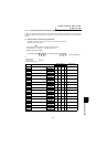
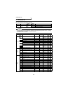
2.7.9 Pulse monitor selection (Pr. 430)
The states of various pulses during operation are displayed in terms of the number of pulses.
Set "6" in Pr. 52 "DU/PU main display data selection" to display output frequency monitor.
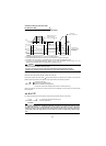
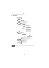
2.7.10 Concept of position control gains
Easy gain tuning is available as an easy tuning method. For easy gain tuning, refer to the Instruction Manual
(basic). If it does not produce any effect, make fine adjustment by using the following parameters. Set "0" in Pr. 819
"easy gain tuning" before setting the parameters below.
(1) Pr. 422 "position loop gain" (factory setting 25s
-1
)
Make adjustment when any of such phenomena as unusual vibration, noise and overcurrent of the motor/
machine occurs.
Increasing the setting improves trackability for the position command and also improves servo rigidity at a stop,
but oppositely makes an overshoot and vibration more liable to occur. Normally set this parameter within the
range about 5 to 50.
(2) Pr. 423 "position feed forward gain" (factory setting 0)
This function is designed to cancel a delay caused by the droop pulses of the deviation counter.
When a tracking delay for command pulses poses a problem, increase the setting gradually and use this
parameter within the range where an overshoot or vibration will not occur.
This function has no effects on servo rigidity at a stop.
Normally set this parameter to 0.
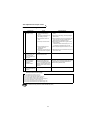
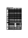
Parameter Name Factory Setting Setting Range Remarks
427 Excessive level error 40 0 to 400, 9999 9999: function invalid
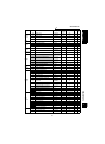
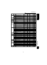
Pr. 430 Description
Display Range
(FR-DU04
-1)
Display Range
(FR-PU04V)
0
The cumulative command pulse value is displayed.
Lower 4 digits Lower 5 digits
1 Upper 4 digits Upper 5 digits
2
The cumulative feedback pulse value is displayed.
Lower 4 digits Lower 5 digits
3 Upper 4 digits Upper 5 digits
4
The droop pulses are monitored.
Lower 4 digits Lower 5 digits
5 Upper 4 digits Upper 5 digits
9999 The frequency monitor is displayed. (factory setting)
REMARKS
• Count the number of pulses when the servo is on.
• The cumulative pulse value is cleared when the base is shut off or the clear signal is turned on.
Related parameters
Pr. 52 "DU/PU main display data selection" (Refer to page 97.)
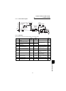
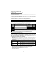
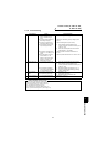
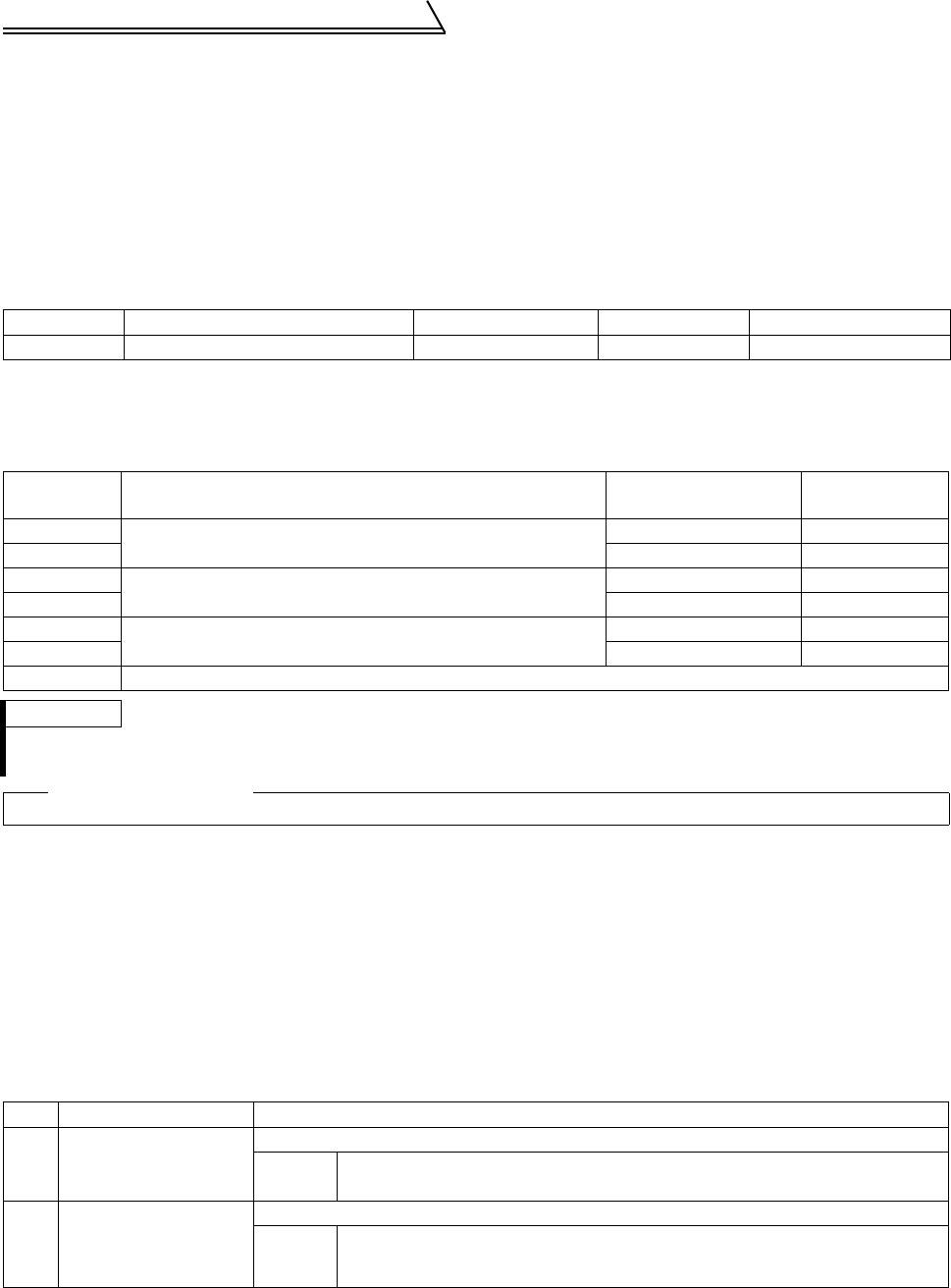
No.
Phenomenon/Condition
Adjustment Method
1 Slow response
Increase the Pr. 422 value.
Pr. 422
Increase the value 3s
-1
by 3s
-1
until just before an overshoot, stop-time vibration
or other instable phenomenon occurs, and set about 0.8 to 0.9 of that value.
2
Overshoot, stop-time
vibration or other
instable phenomenon
occurs.
Decrease the Pr. 422 value.
Pr. 824
Decrease the value 3s
-1
by 3s
-1
until just before an overshoot, stop-time vibration
or other instable phenomenon occurs, and set about 0.8 to 0.9 of that value.