


139
PID control (Pr. 128 to Pr. 134)
PARAMETERS
3
3.14.2 E
2
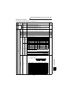
PROM write selection (Pr. 342)
You can select either E
2
PROM or RAM to which parameters to be written during computer link communication
operation (RS-485 communication by PU connector) and operation with a communication option. When changing
the parameter values frequently, write them to the RAM (Pr. 342 = 1).
3.15 PID control (Pr. 128 to Pr. 134)
3.15.1 PID control (Pr. 128 to Pr. 134 )
<Setting>
(1) Basic PID control configuration
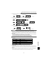
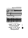
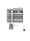
Parameter Name Factory Setting Setting Value
342
E
2
PROM write selection
0
0
Write into E
2
PROM
1 Write into RAM
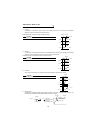
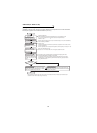
REMARKS
When the parameter setting is " not written to E
2
PROM" (setting = 1), the settings return to the original values (values saved in
the E
2
PROM) at power on reset or terminal reset.
Pr. 342 Setting
0
(factory setting)
E
2
PROM write
Powering off the inverter will not erase the changed parameter values.
1
RAM write
Powering off the inverter will erase the changed parameter values. Therefore, the parameter
values available when power is switched on again are the values stored in E
2
PROM last time.
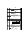
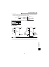
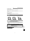
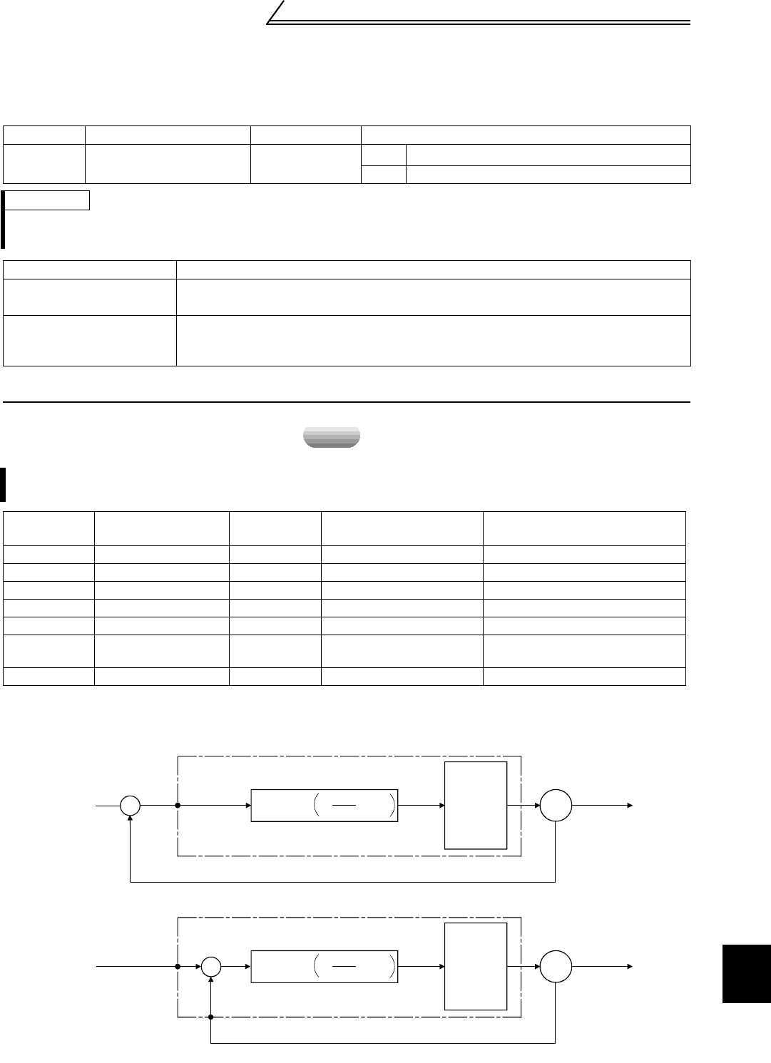
The inverter can be used to exercise process control, e.g. flow rate, air volume or pressure.
z The voltage input signal (0 to ±10V) is used as a feedback value to constitute a feedback system for PID control.
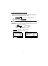
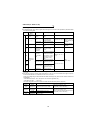
Parameter
Number
Name
Factory
Setting
Setting Range Remarks
128 PID action selection 10 10, 11, 30, 31
129 PID proportional band 100% 0.1 to 1000%, 9999 9999: No proportional control
130 PID integral time 1s 0.1 to 3600s, 9999 9999: No integral control
131 Upper limit 9999 0 to 100%, 9999 9999: Function invalid
132 Lower limit 9999 0 to 100%, 9999 9999: Function invalid
133
PID action set point for
PU operation
0% 0 to 100%
134 PID differential time 9999 0.01 to 10.00s, 9999 9999: No differential control
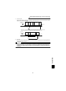
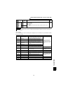
speed
Kp
PID
operation
1 +
Ti·S
1
+ Td·S
x
Deviation
Process
value
fi
Manipulated
variable
Drive
circuit
Motor
IM
Kp: Proportional constant Ti: Integral time S: Operator Td: Differential time
Set
point
Inverter
Terminal 1
Pr.128 = 10, 11
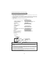
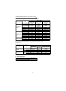
x
Deviation
Process value
fi
Manipulated
variable
IM
Set
point
Terminal 2
Pr.128 = 30, 31
+
-
Drive
circuit
Motor
Inverter
Kp
PID
operation
1 +
Ti·S
1
+ Td·S
Terminal 1