


A-2
2) Wiring
3) Trial run
4) Operation
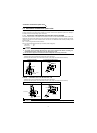
5) Emergency stop
6) Maintenance, inspection and parts replacement
7) Disposing of the inverter
8) General instructions
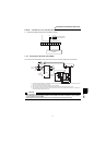
z Do not fit capacitive equipment such as power factor correction capacitor, surge suppressor or radio noise filter (option FR-BIF) to
the inverter output side.
z The connection orientation of the output cables (terminals U, V, W) to the motor will affect the direction of rotation of the motor.
z Check all parameters, and ensure that the machine will not be damaged by a sudden start-up.
z When you have chosen the retry function, stay away from the equipment as it will restart suddenly after an alarm stop.
z Since the [STOP] key is valid only when functions are set (refer to page 115) provide a circuit and switch separately to make an
emergency stop (power off, mechanical brake operation for emergency stop, etc).
z Make sure that the start signal is off before resetting the inverter alarm. A failure to do so may restart the motor suddenly.
z The load used should be a three-phase induction motor only. Connection of any other electrical equipment to the inverter output may
damage the equipment.
z Do not modify the equipment.
z Do not perform parts removal which is not instructed in this manual. Doing so may lead to fault or damage of the inverter.
z The electronic thermal relay function does not guarantee protection of the motor from overheating.
z Do not use a magnetic contactor on the inverter input for frequent starting/stopping of the inverter.
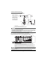
z Use a noise filter to reduce the effect of electromagnetic interference. Otherwise nearby electronic equipment may be affected.
z Take measures to suppress harmonics. Otherwise power supply harmonics from the inverter may heat/damage the power capacitor
and generator.
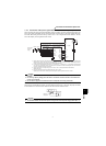
z When a 400V class motor is inverter-driven, please use an insulation-enhanced motor or measures taken to suppress surge
voltages. Surge voltages attributable to the wiring constants may occur at the motor terminals, deteriorating the insulation of the
motor.
z When parameter clear or all clear is performed, each parameter returns to the factory setting. Each parameter returns to the factory
setting.
z The inverter can be easily set for high-speed operation. Before changing its setting, fully examine the performances of the motor and machine.
z In addition to the inverter's holding function, install a holding device to ensure safety.
z Before running an inverter which had been stored for a long period, always perform inspection and test operation. In addition to the
inverter's holding function, install a holding device to ensure safety.
z Provide a safety backup such as an emergency brake which will prevent the machine and equipment from hazardous conditions if
the inverter fails.
z When the breaker on the inverter input side trips, check for the wiring fault (short circuit), damage to internal parts of the inverter, etc.
Identify the cause of the trip, then remove the cause and power on the breaker.
z When the protective function is activated, take the appropriate corrective action, then reset the inverter, and resume operation.
z Do not carry out a megger (insulation resistance) test on the control circuit of the inverter.
z Treat as industrial waste.
Many of the diagrams and drawings in this Instruction Manual (basic) show the inverter without a cover, or partially open. Never operate
the inverter in this manner. Always replace the cover and follow this Instruction Manual (basic) when operating the inverter.
CAUTION
CAUTION
WARNING
CAUTION
CAUTION
CAUTION
CAUTION