86
Operation selection functions 1 (Pr. 17 to Pr. 37)
3.5 Operation selection functions 1 (Pr. 17 to Pr. 37)
3.5.1 Inverter output stop (MRS) (Pr. 17 )
<Wiring example> For sink logic
The setting of this parameter needs to be changed to:
z Stop the motor with a mechanical brake (e.g.
electromagnetic brake);
z Provide interlocks to prevent the inverter from
running if the start signal is input to the inverter; or
z Coast the motor to a stop.
Parameter Name Factory Setting
Setting
Range
MRS Signal Specifications Remarks
17 MRS input selection 0
0 Output stops when MRS signal turns on.
Extended
mode
2
Output stops when MRS signal turns off.
(NC contact input specifications)
REMARKS
• Set the MRS signal using the input terminal function selection (Pr. 180 to Pr. 183, Pr. 187).
• The setting cannot be changed during operation.
• Refer to the Instruction Manual (basic) for inverter reset.
CAUTION
• When Pr. 30 = 2 (FR-HC connection), use the X10 signal.
• When the operation mode is the NET mode and Pr. 338 = 0, the MRS signal is used as both the external
terminal and communication-based signals, and the output stops when either signal turns on. At the
Pr. 17 setting of 2, the output stops when either signal turns off. (Oppositely, at the Pr. 17 setting of 2,
both the external terminal and communication-based signals should turn on to make a start.)
Related parameters
• Starting speed setting ⇒ Pr. 13 "starting speed" (Refer to page 84.)
• MRS signal terminal assignment
⇒ Pr. 180 to Pr. 183, Pr. 187 (input terminal function selection) (Refer to page 150.)
Pr. 19 Refer to Pr. 3 (page 77)
Pr. 20, Pr. 21 Refer to Pr. 7, Pr. 8 (page 78)
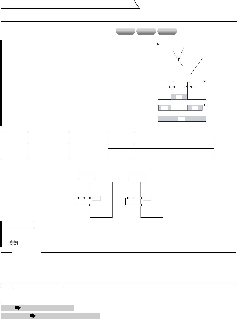
speed torque position
Output
speed
Motor is coasted to stop.
Start at starting speed
About 20ms
ON
When Pr. 17 = 0
Across MRS-SD
Across STF-SD
(STR)
OFF
When Pr. 17 = 2
cross MRS-SD
About 20ms
ON ON
ON
Setting 0 Setting 2
(factory setting)
Output
stop
MRS
SD
Inverter
Output
stop
MRS
SD
Inverter


