


97
Display functions 1 (Pr. 52 to Pr. 56)
PARAMETERS
3
3.7 Display functions 1 (Pr. 52 to Pr. 56)
3.7.1 Monitor display/DA1, DA2 terminal function selection
(Pr. 52 to Pr. 54, Pr. 158 )
<Setting>
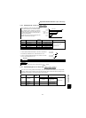
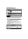
Any of the following signals can be monitored by parameter setting.
The signals marked
× cannot be selected for monitoring.
During operation, you can select the signals shown on the control panel (FR-DU04
-1)/parameter unit (FR-
PU04V) main display screen and on the parameter unit (FR-PU04V) level meter and the signals output to the
DA1 and DA2 terminals.
• There are two analog output DA1 and DA2 terminals.
Select the signals using Pr. 54 and Pr. 158.
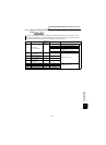
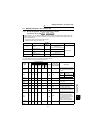
Parameter Name
Factory
Setting
Setting Range Remarks
52
DU/PU main display data
selection
0
0, 5 to 12, 17 to 20, 23, 24,
32 to 35, 38, 100
(5 to 12 are invalid for FR-PU04V)
Extended mode
53
PU level display data
selection
1 0 to 3, 5 to 12, 17, 18
54
DA1 terminal function
selection
1
1 to 3, 5 to 12, 17, 18, 21,
32 to 34, 36
158
DA2 terminal function
selection
1
1 to 3, 5 to 12, 17, 18, 21,
32 to 34, 36
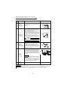
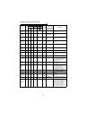
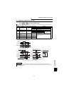
Signal
Type
Display
Unit
Parameter Settings
± Output
Full-Scale Value
of the Level
Meter Connected
to DA1 and DA2
Description
Pr. 52 Pr. 53 Pr. 54 Pr. 158
DU LED
PU main
monitor
PU level
meter
DA1
terminal
12 bits
(±10V)
DA2
terminal
12 bits
(+10V)
No display —— ××0 × ——
When "0" is set in Pr. 53, the level
meter of the parameter unit is not
displayed.
Speed
0.1
r/min
0/100 0/100 1 1 Pr. 55
Output
current
0.01A 0/100 0/100 2 2
× Pr. 56
The output current is displayed as
effective value.
Output
voltage
0.1V 0/100 0/100 3 3
× 400V/800V
The output voltage is displayed as
effective value.
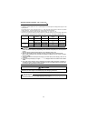
Alarm
display
—— 0/100 0/100
×× × —— ————
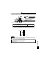
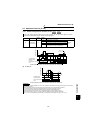
Set speed
0.1
r/min
5*25 5
× Pr. 55
Under speed control, the current
speed setting is displayed.
0r/min under position control.
Output
frequency
0.01
Hz
6*26 6
The frequency
converted from Pr.
55
The output frequency is displayed.
Motor
torque
0.1% 7 *2 7 7 Pr. 866
The output torque is displayed. The
ratio to the rated torque is displayed.
When the DA1 output monitor is
used, a positive voltage is output
during forward driving and reverse
regeneration and a negative
voltage is output during reverse
driving and forward regeneration.
Converter
output
voltage
0.1V8*28 8
× 400V/800V DC bus voltage is displayed.
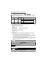
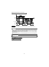
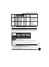
speed torque position
Vector
control
Speed feedback value
from encoder
V/F
control
Speed calculated from
output frequency