


9
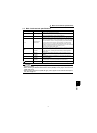
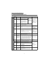
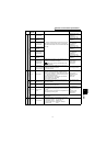
Control circuit terminal specifications
WIRING
1
* Not output during inverter reset.
Input signals
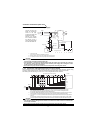
Encoder signal
PA
A-phase signal
input terminal
A-, B- and Z-phase signals are input from the encoder.
The jumper connector is factory-set to complimentary.
Thus, the encoder need not be connected to PAR, PBR
and PZR.
Differential line receiver
input (AM26LS32
equivalent) or
complimentary input
PAR
A-phase inverted
signal input
terminal
Differential line receiver
input (AM26LS32
equivalent)
PB
B-phase signal
input terminal
Differential line receiver
input (AM26LS32
equivalent) or
complimentary input
PBR
B-phase inverted
signal input
terminal
Differential line receiver
input (AM26LS32
equivalent)
PZ
Z-phase signal
input terminal
Differential line receiver
input (AM26LS32
equivalent) or
complimentary input
PZR
Z-phase inverted
signal input
terminal
Differential line receiver
input (AM26LS32
equivalent)
PG
Encoder power
supply terminal
(Positive side)
Power supply for encoder. You can switch the power
supply between 5 (5.5), 12 and 24VDC. Can be
switched to the external power supply.
( Refer to the instruction manual (basic) for the
switchover method.)
5.5VDC 350mA
12VDC 150mA
24VDC 80mA
SD
Contact input
common (sink),
Power supply earth
(ground) terminal
Common terminal for contact input or encoder power
supply.
Isolated from terminals 5 and SE.
Do not earth (ground).
Power supply common
Output signals
Contact
A, B, C Alarm output
1 changeover contact output indicating that the output
has been stopped by the inverter protective function.
230VAC 0.3A, 30VDC 0.3A. Alarm: discontinuity across
B-C (continuity across A-C), normal: continuity across
B-C (discontinuity across A-C).
The terminal function varies with the output terminal
function selection (Pr. 195) setting.
Refer to page 152 for details.
Contact output
Permissible contact
230VAC 0.3A
30VDC 0.3A
Open
collector
DO1 to
DO3
Digital output
terminals 1 to 3
The terminal functions vary with the output terminal
function selection (Pr. 190 to Pr. 192) settings. Refer to
page 152 for details.
Open collector output
Permissible load 24VDC
0.1A
SE
Open collector
output common
Common terminal for terminals DO1, DO2 and DO3.
Isolated from terminals SD and 5.
—
Analog
DA1, DA2
Analog signal
output
One selected from monitoring items, such as the speed,
is output.
*
The output signal is proportional to the magnitude of the
corresponding monitoring item.
0 to ±10VDC (DA1),
0 to 10VDC (DA2),
Permissible load current
1mA
Resolution 12 bit
load impedance
10kΩ or more
5
Analog signal
output common
Common terminal for DA1 and DA2. Isolated from terminals SD and SE. Do not
earth (ground).
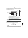
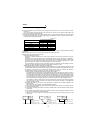
Communication
RS-485
— PU connector
With the PU connector, communication can be made
through RS-485.
• Conforming standard : EIA-485 (RS-485)
• Transmission format : Multidrop link
• Communication speed : Maximum. 19200bps
• Overall length : 500m
Type
Terminal
Symbol
Terminal Name Description Rated Specifications