


106
Brake sequence (Pr. 60, Pr. 278 to Pr. 285)
3.10 Brake sequence (Pr. 60, Pr. 278 to Pr. 285)
3.10.1 Brake sequence function (Pr. 60, Pr. 278 to Pr. 285 )
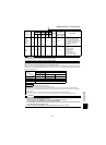
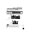
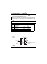
(1) Wiring example
The inverter automatically sets appropriate parameters for operation.
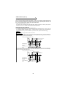
This function is used to output from the inverter the mechanical brake opening completion signal timing signal
in elevator and other applications.
This function prevents the load from dropping with gravity at a start due to the operation timing error of the
mechanical brake or an overcurrent alarm from occurring at a stop, ensuring secure operation.
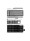
POINT
Set "7" or "8" in Pr. 60.
Set any of "0, 2, or 4" in Pr. 800 "control system selection" under external operation and set speed control.
(Refer to page 169)
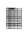
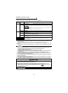
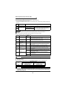
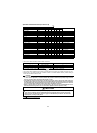
Parameter Name
Factory
Setting
Setting Range Remarks
60 Intelligent mode selection 0 0, 7, 8
Extended mode
278 Brake opening speed 20r/min 0 to 900r/min
279 Brake opening current 130% 0 to 200%
280 Brake opening current detection time 0.3s 0 to 2s
281 Brake operation time at start 0.3s 0 to 5s
282 Brake operation speed 25r/min 0 to 900r/min
283 Brake operation time at stop 0.3s 0 to 5s
284 Deceleration detection function selection 0 0, 1
285 Overspeed detection speed 9999 0 to 900r/min, 9999
CAUTION
When brake sequence mode is selected, automatic restart after instantaneous power failure is invalid.
CAUTION
The I/O signal terminal used differs according to the parameter settings. (Refer to page 150, 152.)
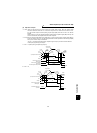
speed
Brake opening request signal (BOF)
* Note the permissible current of the inverter's
internal transistor.
(24VDC 0.1A)
Mechanical
brake
U
V
W
Motor
MC
STF
DI3
DI4
(Caution)
SD
(Caution)
DO1
SE
MC
MC
24VDC
Start signal
Multi-speed signal
Brake opening completion signal
(BRI signal)
MCCB
Sink logic
Pr.183=15
Pr.190=20
Power supply
*
R
S
T