


8
Control circuit terminal specifications
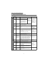
1.4 Control circuit terminal specifications
Type
Terminal
Symbol
Terminal Name Description Rated Specifications
Input signals
Contact input
STF
Forward rotation
start
Turn on the STF signal to start
forward rotation and turn it off to
stop.
When the STF and
STR signals are
turned on
simultaneously, the
stop command is
given.
Input resistance 4.7kΩ
Voltage at opening 21 to
27VDC
Current at short-circuited
4 to 6mADC
Control by open collector
output or 0V contact
signal
STR
Reverse rotation
start
Turn on the STR signal to start
reverse rotation and turn it off to
stop.
The function of the terminals
changes according to the output
terminal function selection
(Pr. 187).
Refer to page 150 for details.
DI1 to DI4
Digital input
terminals 1 to 4
The function of the terminals changes according to the
output terminal function selection (Pr. 180 to Pr. 183).
Refer to page 150 for details.
OH
Thermal relay
protector input
Temperature sensor terminal input for motor overheat
protection.
OHT error occurs when terminals OH and SD are open.
Input resistance 150kΩ
Voltage at opening 21 to
27VDC
Current at short-circuited
140 to 180mADC
Isolate by photocoupler
RES Reset
Used to reset alarm output provided when protective
circuit is activated. Turn on the RES signal for more than
0.1s, then turn it off.
Recover about 1s after reset is cancelled.
Input resistance 4.7kΩ
Voltage at opening 21 to
27VDC
Current at short-circuited
4 to 6mADC
Control by open collector
output or 0V contact
signal.
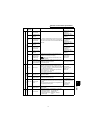
SD
Contact input
common (sink)
Contact input common terminal. Common output
terminal for 24VDC 0.1A power supply (PC terminal).
Isolated from terminals 5 and SE.
—
PC
24VDC power
supply and
external transistor
common, contact
input common
(source)
When connecting a transistor output (open collector
output) such as a programmable controller, connect the
external power supply common for transistor output to
this terminal to prevent a malfunction caused by a sneak
current. PC-SD can be used as a 24VDC and 0.1A
power supply. Note that a sneak current may not be
prevented in this case. When source logic has been
selected, this terminal serves as a contact input
common.
Voltage range 18 to 26
VDC
Permissible load current
0.1A
Speed setting
10E
Speed setting
power supply
Used as power supply when connecting volume for
speed setting (torque setting) from outside of the
inverter. (terminal 5 is a common terminal)
10VDC±0.4V
Permissible load current
10mA
2
Speed setting
(voltage)
By entering 0 to 10VDC, the maximum output speed is
reached at 10V and I/O are proportional.
Input resistance
10kΩ±1kΩ
Permissible maximum
voltage 20VDC
3
Torque setting
terminal
Acts as a torque setting signal for torque control or as a
torque limit signal for speed control or position control.
Acts as an input terminal for the external analog-based
torque bias function.
0 to ±10VDC input
1
Multi-function
setting terminal
Since this is a multi-function selection terminal, its
function varies with the Pr.868 "terminal 1 function
assignment" setting. Refer to page 183 for details.
0 to ±10VDC input
5
Speed setting
common, Analog
signal output
common
Common terminal for speed setting signal (terminal 2, 1
or 3) or DA1 and DA2.
Isolated from terminals SD and SE. Do not earth
(ground).
—