


153
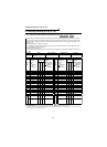
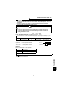
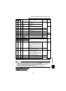
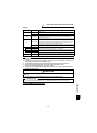
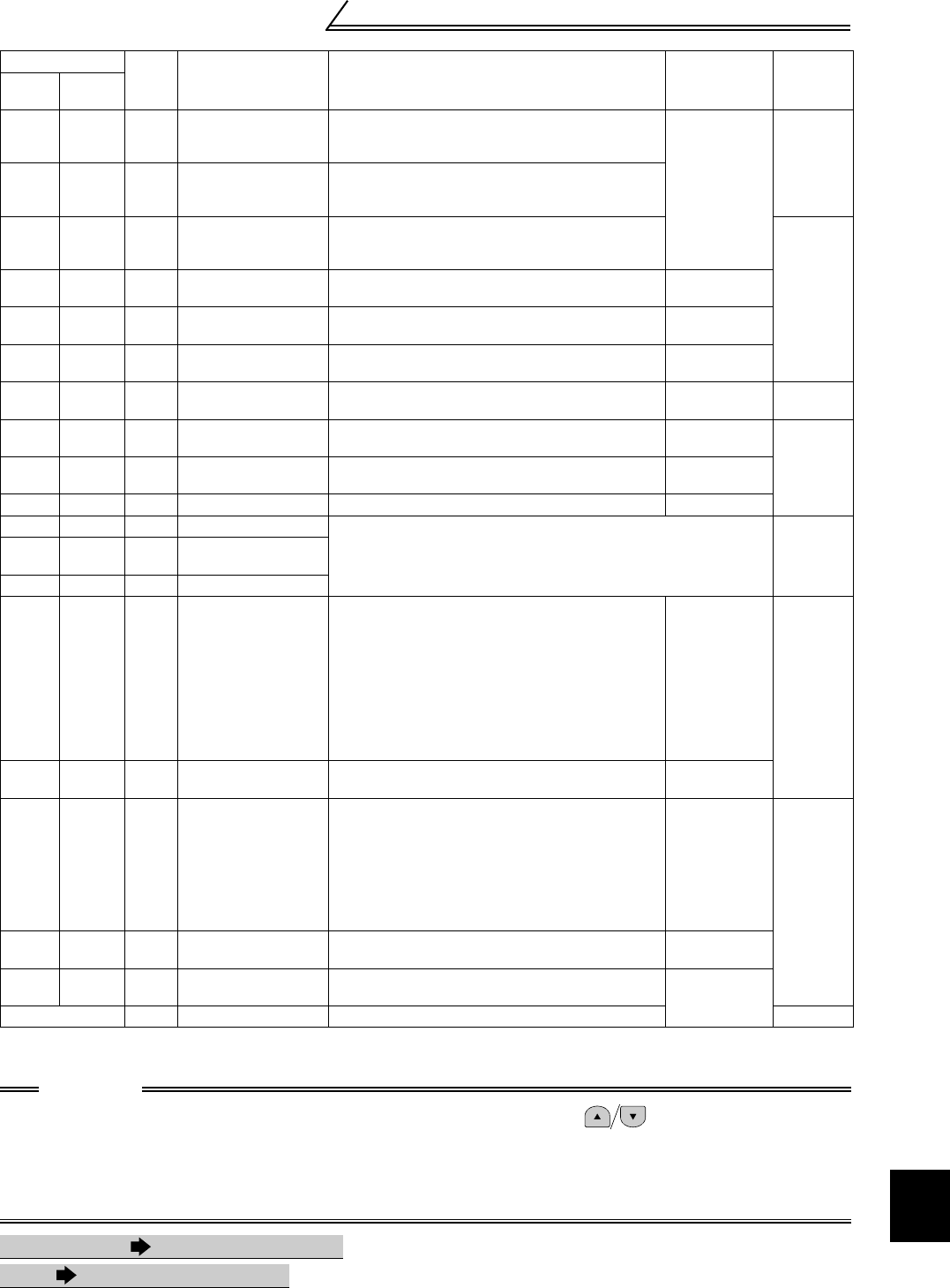
Terminal assignment functions (Pr. 180 to Pr. 195)
PARAMETERS
3
0 to 99: Positive logic
100 to 199: Negative logic
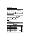
30 130 Y30
Forward rotation
output
Under vector control
ON: forward rotation
OFF: others
⎯
Within
20ms
31 131 Y31
Reverse rotation
output
Under vector control
ON: reverse rotation
OFF: others
32 132 Y32
Regenerative status
output
Under vector control
ON: regeneration
OFF: others (including stop and pre-excitation)
⎯
33 133 RY2 Operation ready 2
Output on completion of pre-excitation. Turned on
at an output start when pre-excitation is not made.
Pr. 802
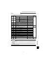
34 134 LS Low speed output
Output when the speed falls to or below any
preset low speed.
Pr. 865
35 135 TU Torque detection
Output when the motor torque rises above the
predetermined value.
Pr. 864
36 136 Y36 In-position
Output when positioning is completed under
position control.
⎯
Within
20ms
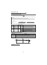
37 137 MT
Maintenance timer
output
When Pr. 891
≥ Pr. 890, the MT output signal
turns on and the warning indication MT appears.
Pr. 890, Pr. 891
⎯
39 139 Y39
Start time tuning
completion
Output on completion of start time tuning.
40 140 Y40 Trace status Refer to the instruction manual of the trace option.
⎯
41 141 FB Speed detection
Output when the inverter output speed rises to or above the preset
speed.
Refer to Pr. 42, Pr.43, Pr. 50, and Pr. 116 (speed detection)
(page 95).
Within
20ms
42 142 FB2
Second speed
detection
43 143 FB3 Third speed detection
44 144 RUN2 Inverter running 2
• Output during forward rotation or the reverse
rotation signal is on.
• Output at deceleration even during forward
rotation or the reverse rotation signal is off.
(Does not output during pre-excitation LX is on.)
• Output during the orientation command signal
(X22) is on.
• Switched on when the servo is on (LX-on) under
position cotrol. (Switched off when the servo is
off. (LX-off)
⎯
⎯
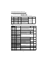
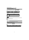
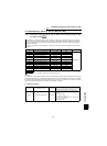
96 196 REM Remote output
You can use the on/off of signals instead of the
remote output function of the PLC.
Pr. 495,
Pr. 496, Pr. 497
97 197 ER
Minor fault output 2
Output when the inverter protective function is
activated to stop the output (major fault) if "0" is
set in Pr. 875 (factory setting).
Output when the inverter's protective function is
activated to start deceleration if "1" is set in Pr.
875 and an OHT/THM/PTC error occurs. Output
when the inverter stops the output if the other
protective functions are activated.
Pr. 875
Within
20ms
98 198 LF Minor fault output
Output when a minor fault (fan fault or
communication error alarm) occurs.
Pr. 121, Pr. 244
99 199 ABC Alarm output
Output when the inverter's protective function is
activated to stop the output (major fault).
⎯
9999 — No function ⎯⎯
CAUTION
1. Note that when the speed setting is varied using an analog signal or of the control panel, the
output of the SU (up to speed) signal may alternate on and off depending on that varying speed and
the timing of the varying speed due to acceleration/deceleration time setting.
(The output will not alternate on and off when the acceleration/deceleration time setting is "0s".)
2. The same function may be set to more than one terminal.
3. Pr. 190 to Pr. 192 and Pr. 195 do not function if the values set are other than the above.
Pr.232 to Pr.239 Refer to Pr. 4 (page 77).
Pr.240 Refer to Pr. 72 (page 112).
Setting
Signal
Name
Function Operation
Related
Parameters
Response
Time
Positive
logic
Negative
logic