132
Communication functions (Pr. 117 to Pr. 124, Pr. 342)
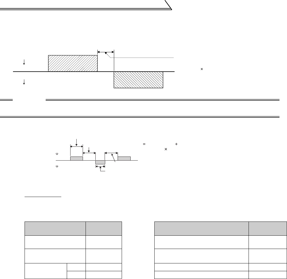
5) Waiting time
Specify the waiting time between the receipt of data by the inverter from the computer and the transmission of
reply data from the inverter. Set the waiting time in accordance with the response time of the computer
between 0 and 150ms in 10ms increments. (Example: 1 = 10ms, 2 = 20ms)
6) Response time
[Formula for data sending time]
zCommunication specifications zData check time
CAUTION
When the Pr. 123 "waiting time setting" setting is other than 9999, create the communication request data
without "waiting time" in the data format. (The number of characters decreases by 1.)
1
×
Number of data
characters
(Refer to page 130)
×
Communication specifications
(total number of bits) = Data send time (s)
(See below.)
Communication
speed (bps)
Name
Number of
Bits
Item Check Time
Stop bit length
1 bit
2 bits
Various monitors, run command,
frequency setting (RAM)
< 12ms
Data length
7 bits
8 bits
Parameter read/write, frequency setting
(E
2
PROM)
< 30ms
Parity check
Yes 1 bit Parameter clear/all clear < 5s
No 0 Reset command No answer
In addition to the above, 1 start bit is necessary.
Minimum number of total bits....... 9 bits
Maximum number of total bits...... 12 bits
Inverter data processing time
= waiting time + data check time
(set value 10ms) (12ms)
Computer
Inverter
Inverter
Computer
10ms or more necessary
Computer
Inverter
Inverter
Computer
Data sending time (refer to the following formula)
Inverter data processing time
Data sending time (refer to the following formula)
Waiting time
(setting 10ms)
Data check time
(depends on the
instruction code (see the
following table))
Time


