


192
Calibration functions (Pr. 900 to Pr. 920)
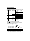
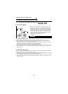
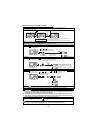
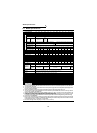
(4) Set the gain speed in Pr. 903 and display the analog voltage value across terminals 2-5 in %.
(To change to 1000r/min)
• When not adjusting the gain voltage → To (5)-1
• When adjusting any point by application of voltage → To (5)-2
• When adjusting any point without application of voltage → To (5)-3
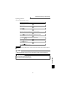
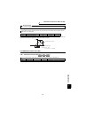
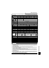
(5)-1 Method to adjust only the gain speed and not to adjust the voltage
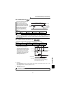
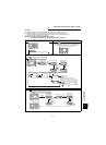
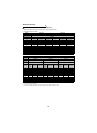
(5)-2 Method to adjust any point by application of voltage to across terminals 2-5 (e.g. applied from external potentiometer)
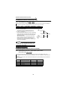
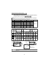
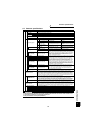
(5)-3 Method to adjust any point without application of voltage to across terminals 2-5(To change from 80% to 100%)
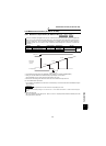
(6) Pressing shifts to the next parameter.
(7) Re-set the Pr. 79 "operation mode selection" value according to the operation mode being used.
CAUTION
1. Changing the Pr. 903 or Pr. 905 (gain adjustment) value will not change the Pr. 20 "acceleration/
deceleration reference speed" value. (Refer to page 78 for Pr. 20.) The input of terminal 1 (speed
setting auxiliary input) is added to the speed setting signal.
2. For the operating procedure using the parameter unit (FR-PU04V), refer to the FR-PU04V instruction manual.
3. When applying voltage for calibration, the difference of the set input voltage of bias and gain should
be 5% or more. If the difference is 5% or less, a setting error will occur.
Take care when setting any value other than "0" as the bias speed at 0V. Even if a speed command is
not given, merely turning on the start signal will start the motor at the preset speed.
SET
FR-DU04
-1
CONTROL PANEL
Hz/r
MON EXT PU
A
V
REV FWD
Currently set gain speed
Gain speed changing
Press for
1.5 s
Analog voltage value (%) across terminals 2-5
Use to change the
preset speed.
In any of the following methods in (5)-1 to (5)-3, continue the setting
until the analog voltage value flickers.
If you end the setting here, the gain speed changing is not reflected.
FR-DU04
-1
CONTROL PANEL
Hz/r
MON EXT PU
A
V
REV FWD
FR-DU04
-1
CONTROL PANEL
Hz/r
MON EXT PU
A
V
REV FWD
SET
Press for 1.5 s.
Flicker
Example: When the analog
voltage adjustment
value is 100% (10V)
Press or once to display the
current analog voltage adjustment value.
Analog voltage value
(%) across terminals 2-5
FR-DU04
-1
CONTROL PANEL
Hz/r
MON EXT PU
A
V
REV FWD
SET
FR-DU04
-1
CONTROL PANEL
Hz/r
MON EXT PU
A
V
REV FWD
Press for 1.5 s
Analog voltage value
(%) across terminals 2-5
Apply a 10V voltage.
(Turn the external potentiometer connected
across terminals 2-5 to the maximum position.)
In the maximum position of the
potentiometer, the value is nearly
100(%).
Flicker
/
Press for 1.5 s
Press or once to
display the current analog
voltage adjustment value.
Press to set the gain voltage (%).
"0V = 0(%), 10V = 100(%)"
Analog voltage value
(%) across terminals 2-5
SET
FR-DU04
-1
CONTROL PANEL
Hz/r
MON EXT PU
A
V
REV FWD
/
Flicker
SET
CAUTION