


28
Input terminals
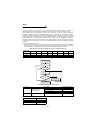
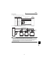
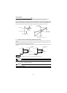
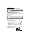
1.7.4 Torque setting input signal and motor-generated torque (terminals 3, 5)
Refer to the diagrams shown at below right for the relationship between the torque setting input signal and output
voltage. The torque setting input signal is in proportion to the output torque. However, motor-generated torque
varies with the motor temperature. The guideline of the output torque accuracy relative to the torque setting input is
torque accuracy ±3% (under condition of 75°C) when the SF-V5RU vector control inverter motor is used.
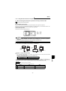
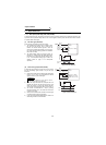
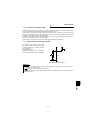
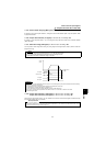
1.7.5 Meter connection method and adjustment (DA1, DA2)
The output speed etc. of the inverter can be displayed by connecting a meter (speed meter) across terminals DA1
(DA2)-5.
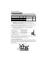
The meter can be calibrated from the control panel or parameter unit. However, if the meter is away from the
inverter, the display value will vary with the wiring distance.
The terminals DA1, DA2 are non-isolated from the control circuit of the inverter. Using a shield cable of within 30m
for wiring.
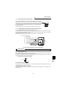
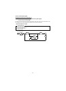
Types of Connected Meters
[Example] To provide a 10V DA1-5 (DA2-5) output of 10V at the inverter output speed of 3000r/min, set "3000" (r/
min) in Pr. 55. (factory setting : 1500r/min)
REMARKS
Using Pr. 867 "DA1 output filter", you can function the primary delay filter. (Refer to page 183.)
CAUTION
Refer to page 188 for the meter adjustment procedure.
CAUTION
Note that when wiring is long, a voltage type meter is susceptible to a voltage drop, induction noise, etc.
and may not read correctly.
Common(-)
3
5
Analog Input Block Diagram
Gain Pr. 905
Bias
Pr.904
0 to ±10VDC
Terminal 3
-150%
10V
-10V
Torque Setting Input vs. Output Torque
Output torque
(Torque command)
150%
Bias
Pr.904
Gain
Pr.905
Meter
(Speed meter)
(-)
DA1
Inverter
Meter
(Speed meter)
(+)
(-)
DA2
Inverter
Zero-center
0 to ±10VDC
0 to 10VDC
(+)
5
5
Load impedance
10k
Ω
or more
Load impedance
10k
Ω
or more