


Performance Tests
CSA 803C Service Manual
4Ć39
This procedure verifies the correct operation and accuracy of the
CSA 803A's trigger system.
Specifications
The specifications for triggering using the external trigger are as follows:
H 100 mV
pĆp
at 300 MHz
H 100 mV
pĆp
at 1000 MHz
H 100 mV
pĆp
at 3.0 GHz
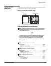
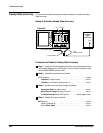
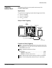
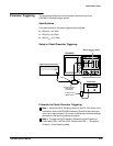
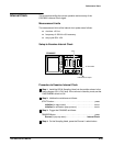
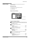
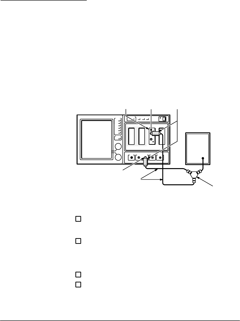
Setup to Check Triggering
CSA 803C
CH 1
Trigger Input
Output
Power Divider
50 W Coaxial Cables
High Frequency
Sine Wave
Generator
2X Attenuators
SDĆ24
Sampling
Head
Procedure to Check Triggering
ăStep 1:ăInstall the SDĆ24 Sampling Head into the position shown in the
setup diagram (CH 1/CH 2 slot). If the unit was in standby mode, set the
ON/STANDBY switch to ON.
ăStep 2:ăInitialize the mainframe as follows:
UTILITY button press...........................................
Initialize (in major menu) touch..............................
Initialize (in verification popĆup menu) touch..................
ăStep 3:ăAdjust the high frequency generator to 400 mV
pĆp
at 300 MHz.
ăStep 4:ăOn the Sampling Head, press the Channel 1 select button.
Triggering,
External Direct