


Corrective Maintenance
Maintenance
6Ć62
A26 M/F Acquisition lnterconnect Board
Removal and replacement Steps are listed below. See Figures 6Ć23, 6Ć25,
6Ć26, 6Ć27, 6Ć28, 6Ć29, and 6Ć32 for connector, screw, and index locations.
ăStep 1:ăRemove the Acquisition unit and position the Acquisition unit in
the upright position.
ăStep 2:ăRemove the A27 Acquisition Analog board, the A28 Acquisition
MPU board, and the A19 Strobe/TDR Buffer board.
ăStep 3:ăRemove the four screws on the gold colored retaining brace
holding the top of the Front Subpanel assembly of the Acquisition unit.
ăStep 4:ăRemove the four screws on the gold colored locking bar located
on the top front of the Acquisition unit.
ăStep 5:ăTurn the Acquisition unit in the inverted position and repeat
Steps 3 and 4 on the bottom of the Acquisition unit.
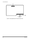
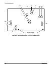
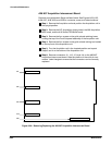
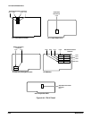
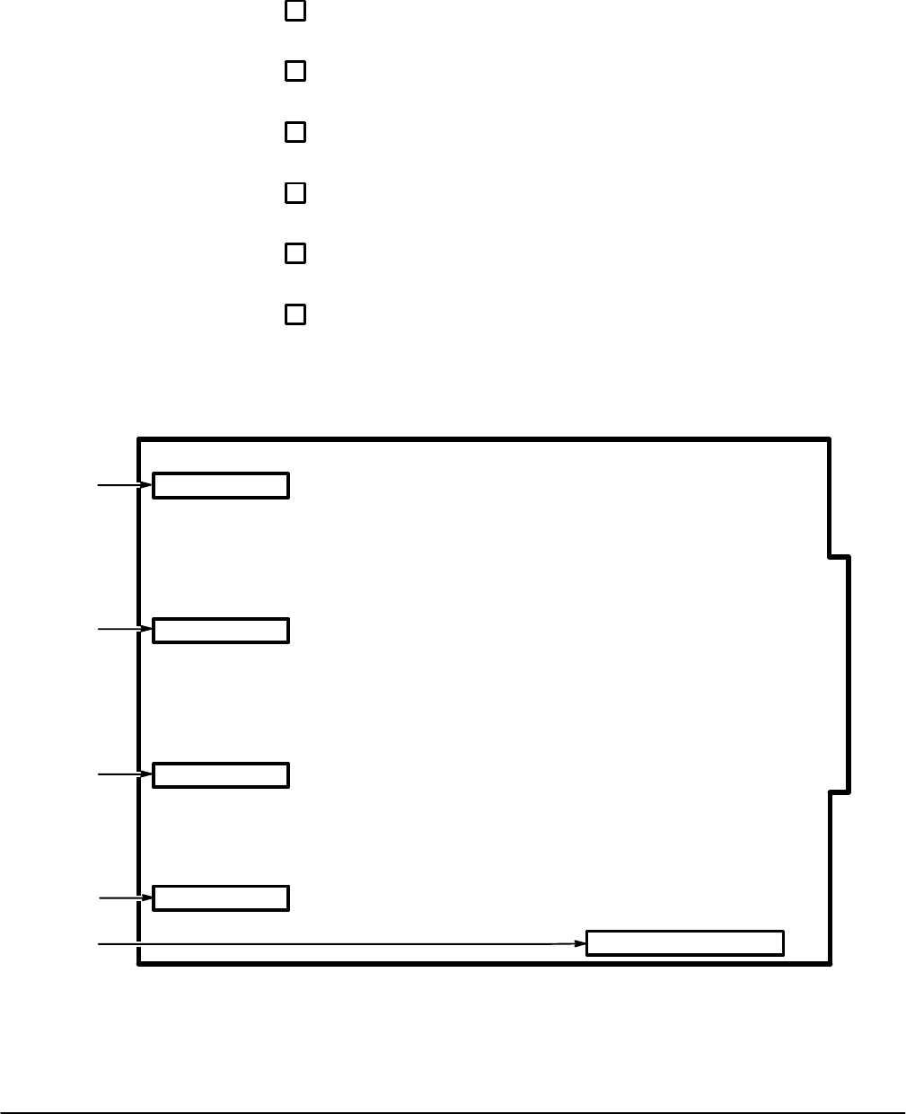
ăStep 6:ăRemove connectors J11, J12, J13, and J14 on the A26 M/F
Acquisition Interconnect board. Note the position of the multiĆpin conĆ
nectors' index triangles to ensure that the connectors can be correctly
replaced.
J11
J12
J13
J14
J10
Figure 6Ć26:ăRemoving/Replacing the A26 M/F Acquisition Interconnect Board