


Diagnostic Troubleshooting
Maintenance
6Ć90
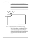
Before a powerĆup SelfĆTest begins Ċ but just after the Executive processor
has run its Kernel Diagnostics Ċ the front panel buttons are scanned by the
Executive processor. If the Executive processor senses that the WAVEFORM
and TRIGGER buttons, and only these two buttons, are pressed in (i.e.,
closed) during this time, then the Executive processor resets its NVRAM to a
default state, the Teksecure Erase Memory function. This essentially deĆ
stroys all stored settings and stored traces in NVRAM. When this occurs, the
NVRAM is initialized by filling all but a few locations with a default value. The
following items are left intact after the NVRAM is reset:
Number of instrument powerĆons (POWERON?)
Instrument power on time (UPTIME?)
Mainframe serial number (UID? MAIN)
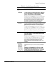
This section correlates Kernel Diagnostic error index codes with the compoĆ
nents or boards suspected of causing each error. The suspect FRU(s) for
SelfĆTest/Extended Diagnostics error index codes are identified by using the
builtĆin FRU help function (?)Help, described under SelfĆTest/Extended
Diagnostics.
The FRU(s) in the Suspect board category in the following error index tables
are listed in mostĆtoĆleast probable cause order. If any diagnostic errors
occur, inspect the suspect FRU for loose connections and components.
Then, repeat the Diagnostic test. If any diagnostic errors occur again, reĆ
place the suspect FRU(s) with a known good FRU or FRUs. Check that the
new FRU is configured exactly like the old one and that any installed firmĆ
ware matches the version in the old FRU.
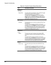
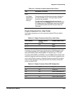
The error index codes and tests are divided into four groups based on the
four processor subsystems: Executive, Display, Time Base, and Acquisition.
Each subsystem group has a table of kernel diagnostic error index codes. In
addition, the Executive has a table of manual test error index codes, which
help extend the confidence level of instrument functionality.
If necessary, kernel error index codes for the Executive and Display can be
read as TTL logic levels on circuit board pins using a logic probe.
Clearing NVRAM
Field Replaceable
Unit (FRU) Guide