


Performance Tests
CSA 803C Service Manual
4Ć27
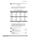
ăStep 11:ăRefer to Table 4Ć3 and check actual results against the table
specifications for the setting levels indicated.
NOTE
Specifications are one percent of full scale at each volts/div setting.
Example: at 5 mV/div full scale for 10 div is 50 mV, which gives an
upper and lower spec tolerance of +0.5 mV and -0.5 mV.
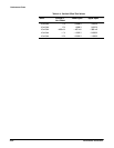
TableĂ4Ć3:ăVoltage Source Settings
Sens.
Source V Lower Spec Upper Spec
5 mV/div
10 mV/div
20 mV/div
50 mV/div
100 mV/div
200 mV/div
-20 mV
-40 mV
-80 mV
-200 mV
-400 mV
-800 mV
-20.5 mV
-41.0 mV
-82 mV
-205 mV
-410 mV
-820 mV
-19.5 mV
-39.0 mV
-78 mV
-195 mV
-390 mV
-780 mV
5 mV/div
10 mV/div
20 mV/div
50 mV/div
100 mV/div
200 mV/div
20 mV
ă40mV
ă80mV
200 mV
400 mV
800 mV
19.5 mV
39.0 mV
78 mV
195 mV
390 mV
780 mV
20.5 mV
41.0 mV
82 mV
205 mV
410 mV
820 mV
NOTE
Up to now, you have been working with trace 1 (Channel 2) and
internal mainframe acquisition measurement channel 1. Use the
following steps to verify the vertical accuracy through internal
acquisition measurement channel 2, using trace 2. (Don't remove
Voltage Source from Calibration Head Channel 2).
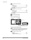
ăStep 12:ăInitialize the mainframe as follows:
UTILITY button press...........................................
Initialize (in major menu) touch..............................
Initialize (in verification popĆup menu) touch..................
ăStep 13:ăTrigger the CSA 803C as follows:
TRIGGER button press.........................................
Source (in major menu) touch...............................
Internal Clock (in popĆup menu) touch.......................