


Corrective Maintenance
CSA 803C Service Manual
6Ć35
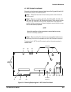
A5 Time Base/Controller Board
A6 Calibrator Board
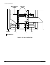
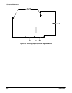
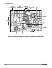
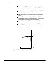
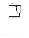
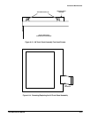
Removal and replacement steps are listed below. See Figures 6Ć10 and 6Ć32
for connector, screw, and index locations.
ăStep 1:ăPlace the instrument in the inverted position.
ăStep 2:ăTo remove the A6 Calibrator Board, remove connectors J1 and
J17 from the A6 Calibrator Board. Remove the Torx head screw securing
the board in place. Lift the board from J91 on the A5 Time Base/ControlĆ
ler Board. Perform this process in reverse to replace the Calibrator
Board.
ăStep 3:ăRemove connectors J16, J29A, J30A, J32, J35, J91, Ext A, and
Presc (if Prescaler is present) from the A5 Time Base/Controller board.
Use extreme care to prevent damage to the cable center connector that
was attached to Presc. Then remove connectors J18 and J83 from the
A5 Time Base/Controller board. Note the position of the multiĆpin conĆ
nector's index triangles to ensure that the connectors can be correctly
replaced.
NOTE
Record the positions of the connectors and the receptacles to
ensure that these connectors and receptacles will be positioned
correctly when reinstalled.
ăStep 4:ăRemove the six Torx head screws holding the board in place.
ăStep 5:ăRemove the A5 Time Base/Controller board.
To replace the board, perform the previous steps in reverse order.