


Adjustments
Adjustment Procedures
5Ć2
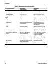
TableĂ5Ć1:ăMeasurement Limits and Adjustments
Procedure Description Measurement
Limits (Examine)
Adjustments
(Adjust)
Power Supply
Voltage Supply +4.85 V to +5.25 V none
Voltage Reference +5.15 V to +5.25 V R800 +5.2 V Ref for +5.20 V
Regulator Reference +9.95 V to +10.05 V R730 +10 V Ref for +10.00 V
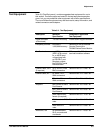
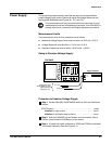
Display
Cutoff visible SCREEN, on transformer on A8
CRT Driver board, until display
appears
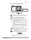
Convergence primary colors are not separated
in the white grid
CONVERGENCE, R210, for
optimum convergence of red,
green, and blue.
Focus focused grid pattern FOCUS, on transformer on A8
CRT Driver board, for optimum
focus on white grid pattern.
Vertical Size and Position align with tic marks VERT SIZE, L321; and VERT POS,
R311; for optimum alignment
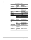
Horizontal Size, Linearity and
Position
align with tic marks and for
optimum appearance
HĆSIZE, R501; HĆLIN, R502; and
HĆPOS, R500; for optimum
alignment and linearity
Gray Scale white at the top of the display,
gray at the bottom, and the right
side of the display is cut off
SCREEN, on transformer on A8
CRT Driver board; RED, R200;
GREEN, R201; and BLUE, R203,
for cutoff and color balance
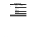
Color Impurity no severe color impurities in red,
green, and blue display
cycle power on and off
Real Time Clock 1,000,000 ms ±5 ms Real Time Clock for 1,000,000 ms