


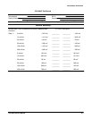

Performance Tests
Performance Verification
4Ć14
This procedure should be performed within the ambient temperature range
of +18_ C to +28_ C (64_ Fto82_ F) when a performance check at peak
operating conditions is required.
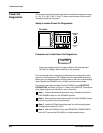
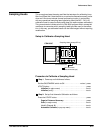
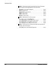
Setup to Invoke PowerĆOn Diagnostics
CSA 803C
(not
installed
yet)
Sampling
Head
Procedure to Invoke PowerĆOn Diagnostics
CAUTION
Applying a voltage outside the range printed on the sampling head
can result in damage. Static electricity is also a hazard.
The input diodes used in the sampling heads are very susceptible to damĆ
age from overdrive signal or DC voltages and from electrostatic discharge.
Never apply a voltage outside the range printed on the front of the sampling
head. Operate the CSA 803C only in a staticĆcontrolled environment.
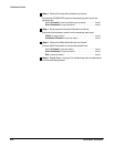
Connect the wrist strap provided with the CSA 803C to the ANTISTATIC
CONNECTION, as shown in Figure 2Ć1. Refer to the CSA 803C CommunicaĆ
tions Signal Analyzer User Manual for more information.
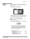
ăStep 1:ăCheck that the sampling head is not yet installed and that the
ON/STANDBY switch is in the STANDBY position.
ăStep 2:ăRemove the top and bottom covers from the CSA 803C (unless
you are only performing a functional test).
ăStep 3:ăInstall an SD Series sampling head in the left sampling head
compartment marked CH 1/CH 2.
ăStep 4:ăWith the CSA 803C's rear panel PRINCIPAL POWER SWITCH
set to OFF, connect the CSA 803C to a suitable power source.
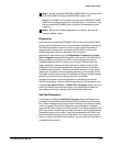
PowerĆOn
Diagnostics