


Corrective Maintenance
Maintenance
6Ć44
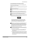
A11 Front Panel Button Board
Removal and replacement steps are listed below. See Figures 6Ć5, 6Ć11,
6Ć15, 6Ć16 and 6Ć32 for connector, screw, and index locations.
ăStep 1:ăRemove the CRT shield. (Refer to the removal instructions
under Cathode Ray Tube Removal/Replacement earlier in this section,
beginning at Step 4.)
ăStep 2:ăRemove connector J75 from the A10 Front Panel Control board.
Note the position of connector's index triangle for correct replacement.
ăStep 3:ăRemove the two Torx head screws from the A11 Front Panel
Button board, which is located at the top and near the inside center of
the front casting.
ăStep 4:ăRemove the A11 Front Panel Button board.
To replace the A11 Front Panel Button board, perform the previous steps in
reverse order.
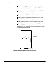
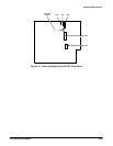
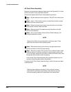
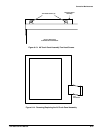
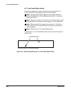
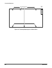
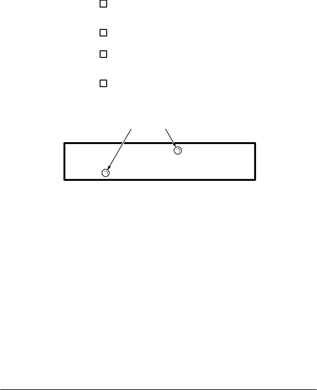
Torx Head Screws (2)
Rear View of the A11 Front Panel Button Board
Figure 6Ć16:ăRemoving/Replacing the A11 Front Panel Button Board