


Corrective Maintenance
Maintenance
6Ć72
ăStep 6:ăUpgrade the A28 Acquisition MPU board firmware as follows:
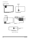
H Remove the Acquisition unit from the instrument.
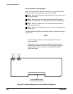
H Remove the A28 Acquisition MPU board from the Acquisition unit
(see Figure 6Ć1 for the exact location of these boards in the AcquisiĆ
tion unit).
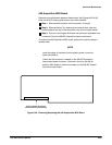
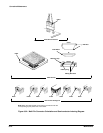
H Locate U611 on the A28 Acquisition MPU board (see Figure 6Ć28).
This board is located in the card cage.
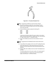
H Replace U611 on the A28 Acquisition MPU board.
The last twoĆdigit portion of the part number on the replacement IC
should be the same as, or higher than, that on the removed IC.
Ensure that pin 1 is oriented correctly.
ăStep 7:ăVerify the instrument serial number as follows:
H Locate the manufacturing jumper, J860, on the A5 Time Base/ConĆ
troller board (see Figure 6Ć10), and install the terminal connector
link.
H Connect a power cord to the instrument.
H Connect a terminal or controller to the CSA 803C. Refer to the CSA
803C User Manual for more information on this connection.
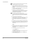
H Set the PRINCIPAL POWER SWITCH and ON/STANDBY switch to
ON.
H Set necessary communication parameters; for example, baud rate.
H After the instrument is poweredĆon, to establish communication from
the terminal or controller, enter the following commands (
<CR> is
the return key):
e
<CR>
v<CR>
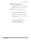
H Verify that the serial number on the instrument's front panel matches
the mainframe ID number in the Identify popĆup menu in the UTILĆ
ITY major menu.
H If the numbers do not match, then enter the command:
uid main:BXXXXXX"
<CR>
where XXXX corresponds to the serial number digits found on the
front panel serial number marker.
H Verify that the proper ID is now displayed in the Identify popĆup
menu, in the Utility major menu.