


Corrective Maintenance
Maintenance
6Ć32
A3 M/F Power Connect Board
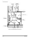
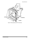
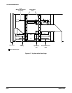
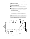
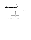
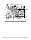
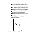
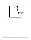
Removal and replacement steps are listed below. See Figures 6Ć2, 6Ć3, 6Ć9
and 6Ć19 for connector, screw, and index locations.
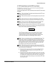
ăStep 1:ăRemove the Power Supply module as described earlier in this
section.
NOTE
The chassis ground (greenĆyellow) wire may be removed from the
Power Supply module for this operation only.
Record the positions of all connectors to ensure that the connecĆ
tors can be correctly replaced.
ăStep 2:ăRemove the A1 M/F Strobe Drive board.
ăStep 3:ăRemove the A5 Time Base/Controller board.
ăStep 4:ăRemove the A4 Regulator board.
ăStep 5:ăRemove J90 from the A14 Input/Output board.
To replace the A3 M/F Power Connect board, perform the previous steps in
reverse order.
WARNING
To prevent electric shock or damage to the instrument, check that
the chassis ground wire is replaced on the Power Supply module.