


Corrective Maintenance
CSA 803C Service Manual
6Ć17
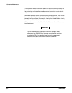
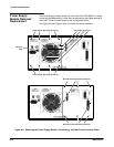
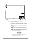
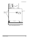
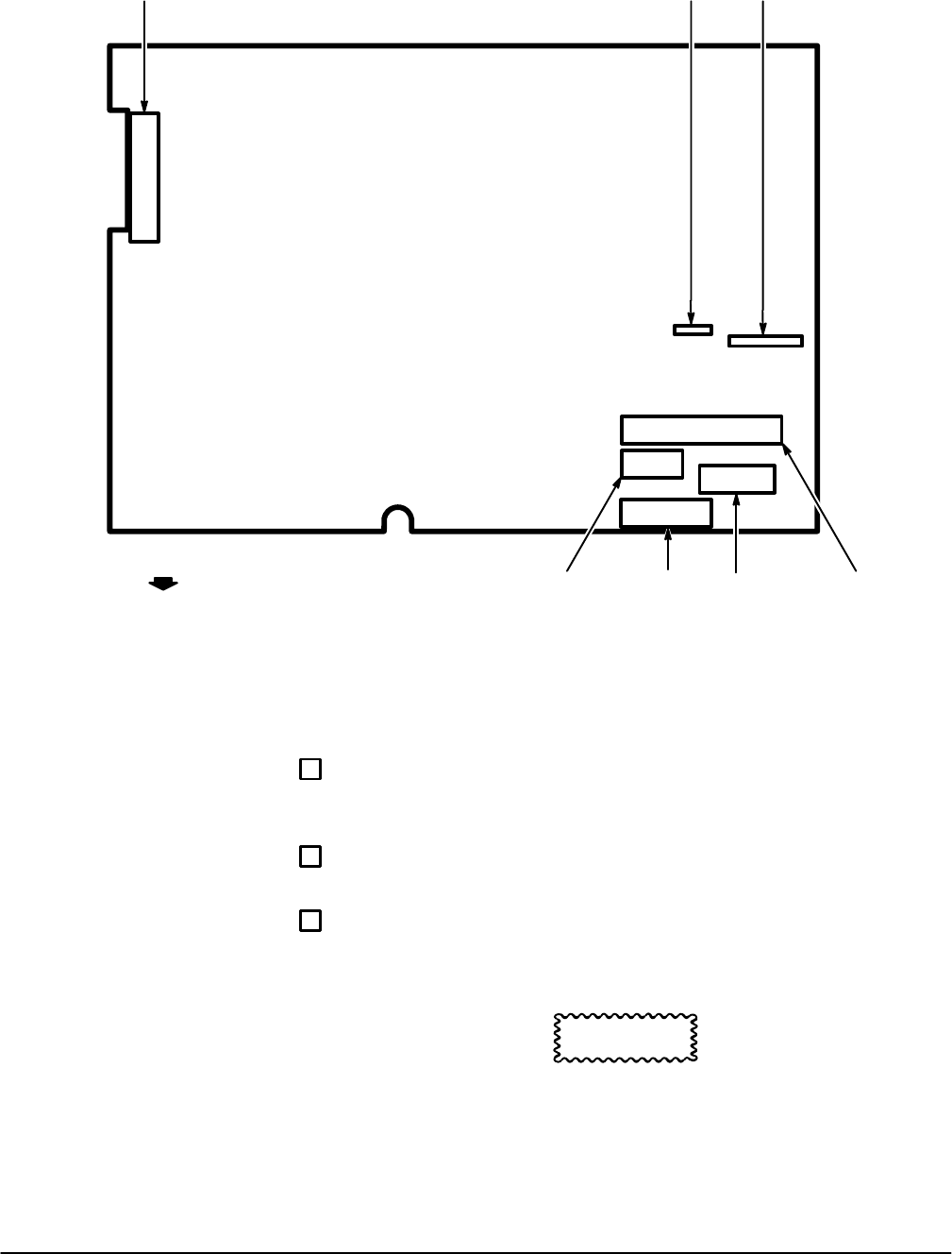
J81 J65J70
J66J63J64 J62
Power Supply
Module Rear
Figure 6Ć3:ăA2A2 Control Rectifier Board Connector Locations
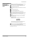
To remove the Power Supply module from the CSA 803C, proceed as folĆ
lows:
ăStep 1:ăTurn the instrument on its left side (as viewed facing the rear
panel). The Power Supply module will now be at the bottom of the
instrument.
ăStep 2:ăRemove the eight Torx head screws that secure the power
supply module.
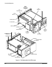
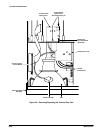
ăStep 3:ăCarefully pull the Power Supply module partially out of the
instrument. Stop short of stretching taut or binding the wires from the
A2A2 Control Rectifier board connectors.
CAUTION
To prevent damage to the connector pins, pull the Power Supply
module only partially out of the instrument.