


Corrective Maintenance
CSA 803C Service Manual
6Ć29
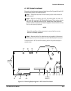
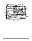
Pin connectors are for electrical interconnection with chassisĆmounted
components and other boards. Most boards/assemblies in the instrument
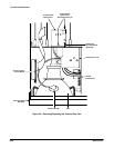
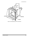
are mounted on the chassis. The following four boards plug onto the top of
the A13 Mother board (see Figure 6Ć7 for the location of these boards in the
card cage):
H A14 Input/Output (I/O)
H A15 Memory Management Unit (MMU)
H A17 Executive Processor (EXP)
H A18 Memory
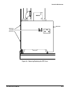
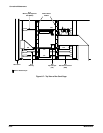
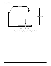
The following two boards plug onto the A26 M/F Acquisition Interconnect
board (See Figure 6Ć1 for the locations of these boards in the Acquisition
unit):
H A27 Acquisition Analog
H A28 Acquisition MPU
FeedĆthrough connectors join the plugĆon boards to the A13 Mother board
and the A26 M/F Acquisition Interconnect board.
CAUTION
To minimize the chance of static charge damage to the integrated
circuits and/or related circuitry, after removing a board from the
instrument, place it on a grounded, antistatic surface.
Some components that are mounted on a board must be retained
for use with the new assembly. These components would include
interconnecting plugs, support posts, and some wiring.
FRU Board and
Assembly Removal