


Corrective Maintenance
CSA 803C Service Manual
6Ć53
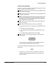
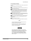
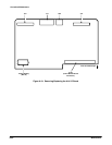
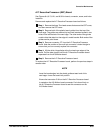
A17 Executive Processor (EXP) Board
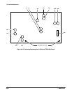
See Figures 6Ć4, 6Ć7, 6Ć21, and 6Ć32 for board, connector, screw, and index
locations.
Remove and replace the A17 Executive Processor board as follows:
ăStep 1:ăRemove the three Torx head screws that secure the CRT cover,
and then remove the CRT cover.
ăStep 2:ăRemove both of the plastic board guides from the top of the
card cage. The guides are retained by two small catches located in two
holes in the left bracket of the card cage. The other ends of the guides
contain slots that attach to the edge of a metal bracket. Both ends of the
guides can be pried loose.
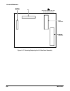
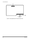
ăStep 3:ăRemove connector J77 from the A17 Executive Processor
board. Note the position of the multiĆpin connector's index triangle to
ensure that you can correctly replace this connector.
ăStep 4:ăLift the white, hinged tabs at the front and rear edges of the
board. Pull the tabs upward until the A17 Executive Processor board
separates from the A13 Mother board.
ăStep 5:ăRemove the A17 Executive Processor board.
To replace the A17 Executive Processor board, perform the previous steps in
reverse order.
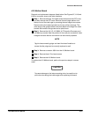
NOTE
Insert the board edges into the plastic guides at each end of the
card cage. Lower the board into position.
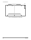
Ensure that connector P104 on the A17 Executive Processor board
is seated on the A13 Mother board connector. Push down firmly on
the A17 Executive Processor board to seat this connector on the
A13 Mother board.