


Corrective Maintenance
CSA 803C Service Manual
6Ć59
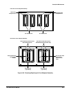
A20/A21 Head Interconnect (Power Only) and
A22/A23 Head lnterconnect Boards
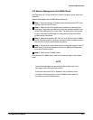
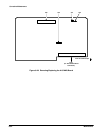
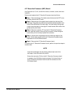
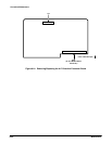
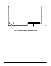
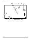
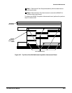
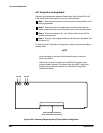
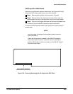
Removal and replacement steps are listed below. See Figures 6Ć23, 6Ć24,
6Ć25, 6Ć26, 6Ć28, 6Ć29, and 6Ć32 for connector and screw locations.
ăStep 1:ăRemove the Acquisition unit and position the Acquisition unit in
the upright position.
ăStep 2:ăRemove the two Torx head screws on each black retaining
brace located at the top of the Acquisition unit.
ăStep 3:ăRemove the A27 Acquisition Analog board, the A28 Acquisition
MPU board and the A19 Strobe/TDR Buffer board.
ăStep 4:ăRemove the four screws holding the top front subpanel of the
Acquisition unit.
ăStep 5:ăRemove the four screws on the goldĆcolored locking bar loĆ
cated on the top front of the Acquisition unit.
ăStep 6:ăTurn the Acquisition unit in the inverted position and repeat
Step 5 on the bottom of the Acquisition unit.
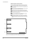
ăStep 7:ăRemove the connectors from the A26 M/F Acquisition InterconĆ
nect board connector. Note the position of the multiĆpin connector's
index triangle to ensure that the connector can be correctly replaced.
ăStep 8:ăRemove the Front Subpanel assembly with the A20ĆA23 Head
Interconnect boards intact.
ăStep 9:ăRemove the bottom Torx head screw from within the sampling
head compartment that contains the head interconnect board you are
removing.
ăStep 10:ăTurn the Front Subpanel assembly around so that the open
compartments face away from you.
ăStep 11:ăRemove the top nut that fastens the sampling head compartĆ
ment to the head interconnect board you are removing.
ăStep 12:ăRemove the Head Interconnect board by slightly prying up on
the tabs that are keeping it in place, and slowly remove the board(s)
from the J1/2/3/4 connector.
To replace the A20/A21 Head Interconnect (Power Only) or the A22/A23
Head Interconnect boards, perform the previous steps in reverse order. Be
sure to replace the Power Only boards at J11 and J12 on the A26 M/F
Acquisition Interconnect board.