


Corrective Maintenance
Maintenance
6Ć64
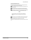
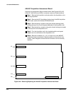
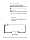
A27 Acquisition Analog Board
Removal and replacement steps are listed below. See Figures 6Ć23, 6Ć26,
6Ć28, and 6Ć32 for board guide, screw, and index locations.
ăStep 1:ăRemove the Acquisition unit and position the Acquisition unit in
the upright position.
ăStep 2:ăRemove the two Torx head screws on each black retaining
brace located at the top of the Acquisition unit to remove these braces.
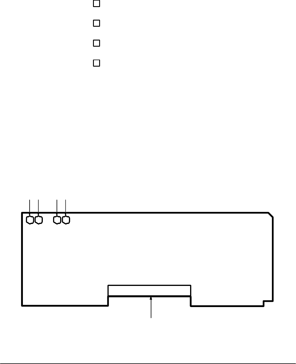
ăStep 3:ăRemove connectors J41, J42, J43 and J44 from the A27 AcĆ
quisition Analog board.
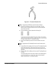
ăStep 4:ăPull up on the hinged white tabs until the board separates from
connector P6.
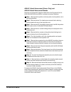
To replace the A27 Acquisition Analog board, perform the previous steps in
reverse order.
NOTE
Insert the edges of the board into the plastic guides. Lower the
board into position.
Check that connector is seated on the A26 M/F Acquisition InterĆ
connect board connector. Push down firmly on the A27 Acquisition
Analog board to seat this connector on the A26 M/F Acquisition
Interconnect board.
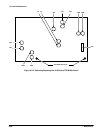
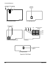
P5/6 (to A26 M/F Acquisition
Interconnect Board Connector)
J41
J42 J43 J44
Figure 6Ć28:ăRemoving/Replacing the A27 Acquisition Analog Board